
Basic Optics
Introduction:
In this module we will learn how matter can act on light, how we can use this to manipulate light propagation. We will learn about reflection, refraction, lenses, lens systems and aberrations.
References:
1. Hecht, Eugene. (1987) Optics. Addison-Wesley Publishing Company, Reading, MA.
2. Pedrotti F and Pedrotti L. (1993) Introduction to
Optics, Prentice-Hall, Upper Saddle River, NJ.
Reflection and Refraction
If a ray of light could be observed approaching and reflecting off of a flat mirror, then the behavior of the light as it reflects would follow a predictable law known as the law of reflection. The diagram illustrates the law of reflection.
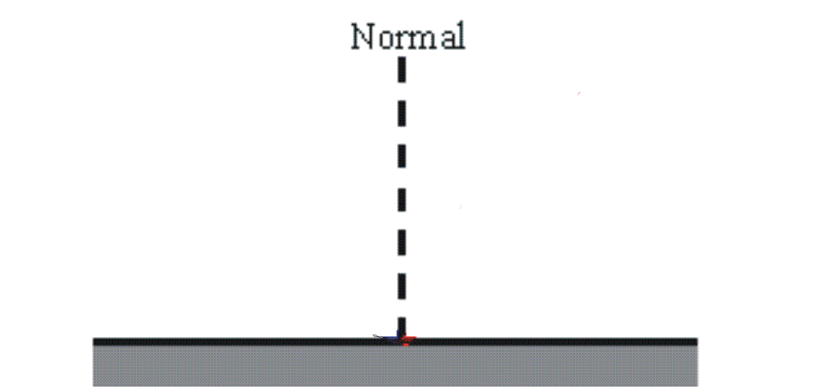
In the diagram, the ray of light approaching the mirror is known as the incident ray (see diagram). The ray of light leaving the mirror is known as the reflected ray. At the point of incidence where the ray strikes the mirror, a line can be drawn perpendicular to the surface of the mirror; this line is known as a normal line. The angle between the incident ray and the normal is known as the angle of incidence, θi. The angle between the reflected ray and the normal is known as the angle of reflection, qr. The law of reflection states that when a ray of light reflects off a surface, the angle of incidence is equal to the angle of reflection, θi = θr.
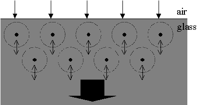
Reflection off of smooth surfaces leads to a type of reflection known as specular reflection. Reflection off of rough surfaces such as clothing, paper, and the asphalt roadway leads to a type of reflection known as diffuse reflection. The diagram below depicts two beams of light incident upon a rough and a smooth surface.

The velocity of light, c, in a vacuum is about 3x10⁸ meters per second. In other media (glass, for example) the velocity is less. The ratio of c to the actual velocity is called the refractive index, n:
![]()
since ,


e = electric permittivity
m = magnetic permeability
ke = dielectric constant (e/eo)
km = relative permeability (m/mo)

The color of the light and its frequency are the same in both media. Therefore, the wavelength must shorten by the same ratio as the velocity. You can think of this "slowing down" of light in a transparent medium if you picture the medium composed of individual atoms or molecules that can interact with the passing light by absorbing and re-emitting the light. This absorbed and re-emitted light is added to the component passing through at c in such a way that the sum is continually slowed down with respect to c. This continuous slowing down is equivalent to a phase velocity less than c.
You can think of it like this: The electrons in the glass are driven to oscillate by the light's E-field. This causes the electrons to become dipoles themselves and they begin to re-radiate or scatter. However, only the wavelets in the forward direction are IN PHASE and interfere constructively. The others interfere destructively and cancel out.
3 Basic Laws
Three fundamental laws describe how a wavefront of light interacts with a surface that forms the boundary between materials with different refractive indices e.g. air-glass interface where air has a refractive index of 1 and glass is typically 1.5.
1) Incident, reflected, and transmitted waves lie all in the same plane
2) Angle of incidence is equal to the angle of reflection
θi = θr
3) SNELL'S LAW:
ni sin(θi) = nt sin(θt)
Where ni is index of refraction of the medium 1 and nt is index of refraction of medium 2

Snell's Law allows us to calculate the new direction of propagation when light passes through an interface between two materials with different indices of refraction. The angles are measured between the normal to the surface and the light beam. Light passing from a material with a high index of refraction to a material with a low index of refraction bends away from the normal whereas light passing from material with a low to material with a high index of refraction bends toward the normal.
Fresnel's Equations
While Snell's law and the law of reflection tell us something about the direction in which reflected and refracted light propagate, it does not say anything about how much light goes where. When light strikes the interface between two materials with different indices of refraction, a fraction of the light is reflected (R) and a fraction is transmitted (T). The values of R and T may be calculated using Fresnel's equations. It is important to realize that 1) the sum of reflected and transmitted light must equal the total incident light (since these are fractions R + T = 1); and 2) the angle of polarization of the incident EM wave with respect to the plane of the incident material has an effect on the respective fractions of light that are transmitted or reflected.
a) E-Field perpendicular to the plane of incidence


r = amplitude reflection coefficient, ratio of reflected to incident electric field amplitudes.

t = amplitude transmission coefficient, ratio of transmitted to incident electric field amplitudes.
b) E-field parallel to the plane of incidence


Given that,
R = Reflectance (W/m2)
T = Transmittance (W/m2)
When there is no absorption, R + T = 1, and

If θi = 0, the incident plane becomes undefined and

![]()
Examples:
1. What percent of light is reflected at the interface of air (n = 1.0) to glass (n = 1.5) if the angle of incidence is 0°?
Answer:


This means that in a lens, which has 2 air-glass interfaces, transmission through each interface = 96%. This means that the transmission through the lens even it absolutely non-absorbing is (0.96)2 = 0.9216. In other words 7.84% of the light is lost due to reflection. Note that this property is multiplicative.
2. What percent of light is transmitted from air (n = 1.0) to glass (n = 1.4) if the angle of incidence is 48°. Assume that the light is unpolarized.
Answer:
The easiest way to approach this is to calculate the fraction of light that is reflected. Assuming no absorption, the remainder is transmitted into the second medium.
First start with calculating the angle of refracted light using Snell's law. Given that
θi = 48°

We can thus calculate the reflection coefficients for parallel and perperdicularly polarized light using Fresnel equations.
Substituting this into:
![]()
Next we have to realize the light is unpolarized. Practically we can handle this in terms of Fresnel's equations by assuming that there is equal quantities of parallel and perpendicularly polarized light and the simply take the average:

Thus R = 4.02%
with T = 1 - R it follows that: T = 1 - 0.0402 = 0.9598
An Application of Fresnel Equations
The Fresnel equations describe the effects of an incoming electromagnetic plane wave on the interface between two media with different dielectric constants or indices of refraction.
From the different Fresnel equations we obtain,

Here, note that while R¡ can never be zero, R// is zero when (θi + θt) = 90°. As a result, for E-field parallel to the plane of incidence, the reflectance vanishes and the beam is completed transmitted. This is Brewster's Law (see figure).

Another way to look at this is that for parallel polarized light, there is an angle of incidence where the reflectivity = 0. This angle, known as the Brewster's angle can be calculated by:
Lenses and Lens Systems
A lens is typically made up of an optically translucent material containing two or more refracting surfaces, at least one of which is curved. Lenses may be used in an optical system to modify a beam of light or to form an image of an object. There are a number of factors that need to be considered when characterizing a lens:
Diameter: The diameter of a lens is typically chosen based on the size of the beam and object that needs to be modified.
Radius of Curvature: R determines how curved the lens is and the direction of the curvature. It also relates to the focal length of the lens (see lens equations section).
Focal length: Focal point is defined as the point at which parallel rays coming into the lens converge. The distance between the center of the lens at this point is the focal length f of the lens. This point may be on the opposite side of the lens as in a convex lens or the same side as in a concave lens.
Transmission range: Any given material will allow light of certain wavelengths to be transmitted while allowing others to be absorbed. The lens material is chosen based on the wavelength of the light that is being modified. e.g. glass transmits well from 400 to 2500 nm, however quartz needs to be used to transmit light in the UV while more exotic materials need to be used for transmission further in the IR (for example: sapphire, CaF2, etc.).
Aberrations: Aberrations are limitations in lens behavior that can be detrimental to its performance. These include spherical aberrations, chromatic aberrations, coma, and astigmatism.
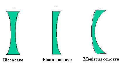
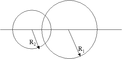
There are six kinds of lenses, divided in two main categories; a) the positive or convex lenses and b) the negative or concave lenses. The convex lenses have in common that they are thicker in the center than at the edge while the concave lenses are thinner in the center than at the edges:

R1 > 0 R1 = ¢ R1 > 0
R2 < 0 R2 < 0 R2 > 0
R1 < 0 R1 = ¢ R1 > 0
R2 > 0 R2 > 0 R2 > 0
where,
R1 = Radius of Curvature of the first lens surface from the left)
R2 = Radius of Curvature of the second lens surface (from the left)
Since all rays issuing from a source point will arrive at the image point, any two rays will fix that point. There are three rays that are easiest to apply. Two of these make use of the fact that a ray passing through the focal point will emerge from the lens parallel to the optical axis and vice versa; the third is the undeviated ray through the center of the lens. They are illustrated below for both positive and negative lenses.

Basic Lens Equations
1) The focal length of a lens can be calculated by the Gaussian Lens Formula:
![]()
where, f = focal length,
o = object distance,
i = image distance
2) Another useful lens equation is the Lensmaker's Formula;
/vbc/images/bme285-module3pics/m3pic32.gif
where nl = index of refraction of the lens
n2 = index of refraction of the surrounding medium typically air)
R1 = Radius of Curvature of the first lens surface from the left)
R2 = Radius of Curvature of the second lens surface (from the left)
3) Transverse Magnification (MT) is defined as the magnification of the image in the direction perpendicular to the direction of propagation and is given as:
![]()
4) Longitudinal Magnification (ML) is defined as the magnification of the image in the direction of propagation and is given as
![]()
5) The transverse magnification of a two-lens system that is separated by a distance d that is greater than the sum of their focal lengths is given by:

The magnification in such a two-lens system is simply the product of the magnifications from each element:
![]()
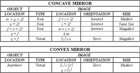
Based on the location of the object relative to the focal point the location, size and type of image will vary for a positive or negative lens.
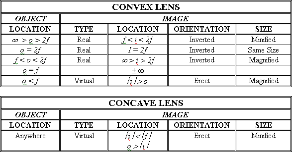
Curved Mirrors behave similar to lenses except that the formation of the image is reversed, i.e. the concave mirror behaves like a convex lens and a convex mirror behaves like a concave lens.
EXAMPLES:
1. Construct the rays to form the image for a positive lens given that the focal length of the lens is 2 m and an object (1.5 m high) is placed at a distance of 3.5 m from the lens.
Answer:
Given,
f = 2 m
o = 3.5 m
h(object) = 1.5 m
(Hint: To construct the image, draw the three rays described earlier)

Given that,
Thus i = 4.67 m
The magnification is given as,
![]()
Therefore, an object 1.5 m high will be magnified 1.33 times to yield an image 1.995 m high. This image is real, inverted and magnified.
2. Construct the rays to form the image for a lens with focal length -10 cm and an object that is placed at a distance of 10 cm from the lens. What kind of image do you get?
Answer:
Given,
o = 10 cm
f = -10 cm, therefore it is a concave (negative) lens.
Draw rays to construct the image.


Therefore i = - 5 cm
The magnification is given as,
![]()
Thus the image is a virtual, erect, minified image located at f/2.
Aberrations
The formulas developed earlier for image formation by spherical reflecting and refracting surfaces are, of course, only approximately correct. In deriving those formulas it was necessary to assume paraxial rays, rays both near to the optical axis and making small angles with it. However, in considering these lens situations will arise when these assumptions are no longer valid and aberrations are observed.
1. Spherical Aberrations
Spherical aberrations occur due to the severe curvature of short focal length or smaller lenses because rays incident on the outer regions of a lens bend more than the rays towards the center, causing the image to appear out of focus.

Spherical aberrations are corrected by:
· using a larger lens
· orienting the lens correctly
· using the right type of lens
2. Coma
Coma is an off-axis aberration that is nonsymmetrical about the optical axis. This arises from the dependence of transverse magnification on the ray height at the lens. Because of coma, an off-axis object point is imaged as a blurred shape that resembles a comet with a head and a tail. This type of image can be minimized by appropriate selection of the diameter of the lens to be used.

3. Astigmatism
When an object point lies far away from the optical axis, the incident cone of rays will strike the lens asymmetrically giving rise to astigmatism. If the rays incident on the lens in the plane of the paper (tangential plane) has a given focal length, then the rays in the plane that is obliquely angled with respect to the paper (sagittal plane) has a different focal length. Thus, for the incident conical bundle of rays, the cross-section of beam as it leaves the lens is initially circular and gradually becomes elliptical until it meets in a line at the focal point that is tangential to the plane of the paper.

4. Field of Curvature
In this type of aberration, a given planar object is imaged on a parabolic surface instead of a plane as can be seen in the figure.

5. Distortion
Distortion shows up as a variation in the transverse magnification for points of the object away from the optical axis. In other words, distortion occurs because different areas of the lens have different focal lengths and different transverse magnifications.

6. Chromatic Aberration
Chromatic aberration occurs for incident rays that contain many wavelengths. Since the index of refraction varies with wavelength, the focal properties of a simple lens will vary as well. The refractive index is higher for blue light than red light. Therefore, the focal length of a convex lens is shorter for blue light than red light.

Chromatic aberration can be corrected for using an achromatic doublet. An achromatic doublet consists of a convex and concave lens made of different materials cemented together. By choosing materials with appropriate refractive indices, you can create a doublet that will have the same focal length at two wavelengths. The two lenses correct for each other and a focal point is found somewhere in the middle.