Flight Projects on Rockets
From 20007 onwards, Vanderbilt Aerospace Design Laboratory has been at the forefront of designing innovative payloads and flight vehicles.
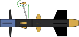
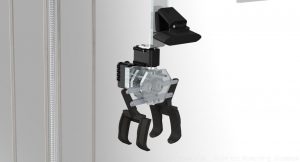
2023: Autonomous Camera Payload for RF Command Imaging
The 2022-23 team is designing an autonomous camera system with several DOF which, upon landing, can receive and process RF signals and execute a set list of commands. This will be achieved through the following order of operations: rocket launch, rocket recovery, leg deployment in flight, landing and parachute detachment, bay rotation, and RF command execution.
.
2022: Modular Payload System For Autonomous Vehicle Location Tracking
The mission of the VADL 2021-2022 team is to design, construct, and fly a vehicle capable of autonomously determining its landing location via computer vision and inertial measurement units without the use of external systems such as GPS. The launch vehicle will be modular and the payload will be versatile such that the project is fully applicable and scalable to a diverse set of interplanetary missions.

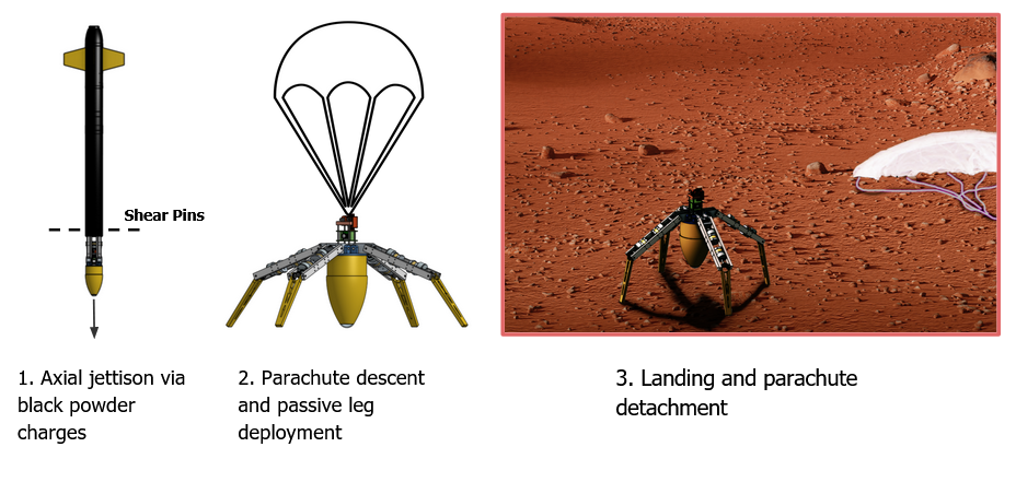
2021 : Vertically Landing and Autonomously Orienting Planetary Imaging System
We are developing the planetary lander MANTIS named for its resilience and bio-inspiration. Mantis is capable of completely jettisoning off a flight vehicle mid-descent and landing upright on four passively deployed legs. Once on the ground, the system will autonomously self-level via actuated motors, capture a 360 degree panoramic image, and transmit the image to the base station. After completing the mission, the lander will then attempt locomotion via actuated legs and transmission of additional panoramic images.
2020-Repeatable, Autonomous, Air-Based Planetary Sample Collection
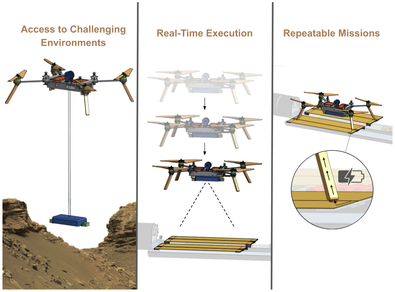
The 2019-2020 proposes to design a mission sequence with three challenges: air-based sampling, autonomous navigation, and UAV recharging. The payload systems will deploy from a ground-based, horizontally-oriented payload bay on the rocket. The payload bay will autonomously reorient until the UAV faces skyward to allow for successful UAV unfolding and deployment. A manual remote input will trigger UAV takeoff. The UAV will then autonomously detect the nearest sampling site and navigate the shortest path to the site.
The UAV will follow an autonomous sampling procedure when it arrives at the sampling site. The sampling tool will be capable of collecting samples from terrains that may be difficult to land on. Sampling will occur with the UAV hovering. After sample collection, the UAV will return to the rocket, where it will deposit the sample and recharge. With sufficient power, the UAV will launch from the rocket and collect a sample from a second sampling site. This will be a reliable and repeatable sequence for long-term space missions which may additionally carry long-term energy storage/conversion devices.
Autonomous navigation will be performed without the use of GPS or a magnetometer, since these devices would not be useful in a real-world space exploration mission. Visual Simultaneous Localization and Mapping (V-SLAM) algorithms will be used to accurately localize the UAV as it flies to the sampling zone and to build a map so the UAV can retrace its path back to the rocket for docking. The system will be robust enough to relocalize in case of tracking failure and will have a manual override in case of a flight failure.
2019-Collaborative UAV Search and Deploy Mission for Space Exploration
The 2018-2019 design team chose to fly two UAV payloads with three team-imposed design challenges: collaborative spatial mapping, image-based guidance and localization, and autonomous navigation. Together, these systems provide the foundation for a UAV payload with potential for space exploration.
Two custom UAVs were flown at competition; each UAV successfully deployed from the rocket and dropped a beacon on the FEA. These UAVs had unique mechanical, electrical, and software systems needed to deploy from the rocket and conduct the computational experiments.
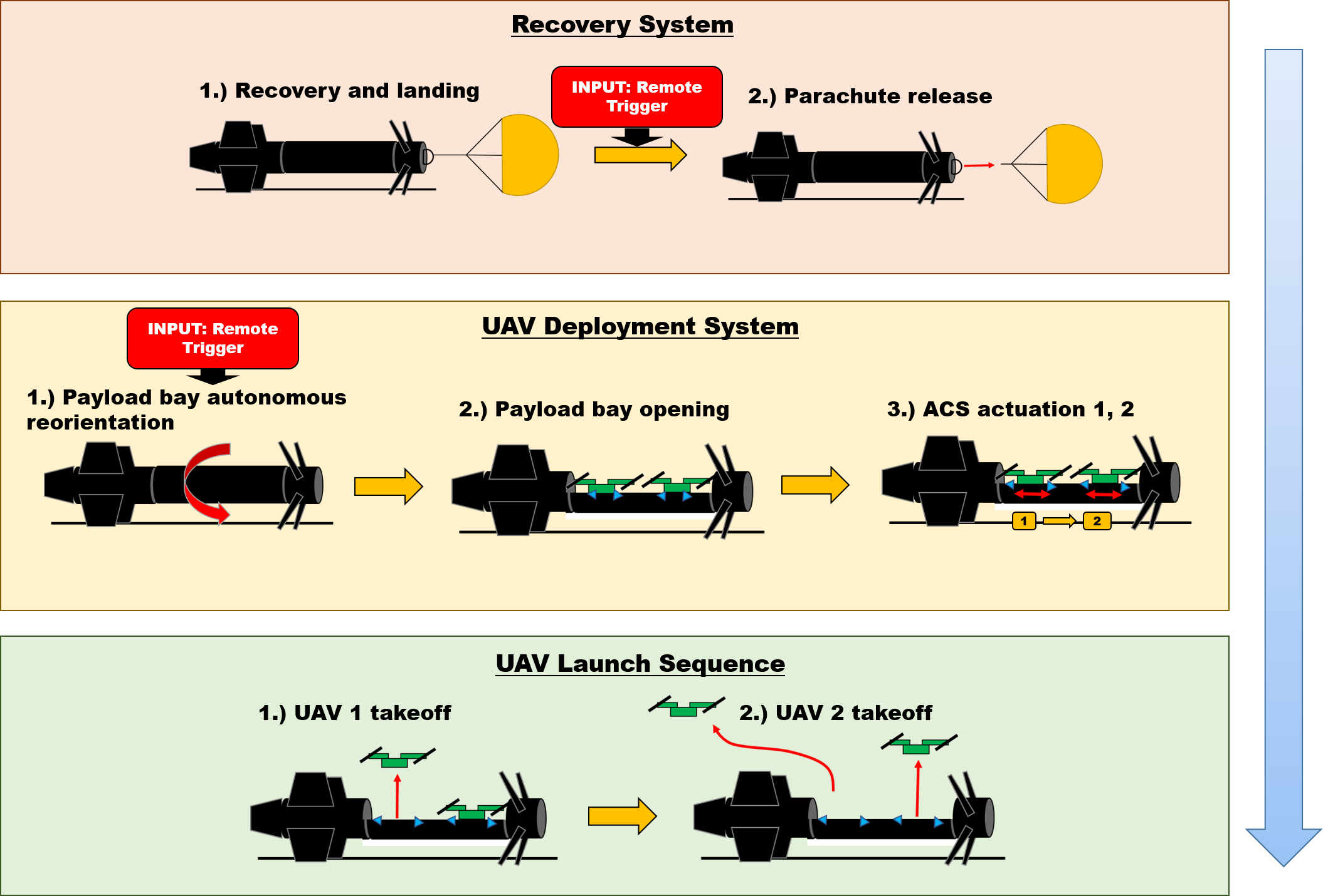
UAV Launch Sequence from Landed Rocket
The VADL UAVs used custom algorithms to run multiple experiments relevant to collaborative exploration of extraterrestrial bodies. These experiments explored communication for collaboration, vision processing for autonomous control and navigation, and target detection for exploration. As these experiments were running, all relevant data was logged, generating about 1.3 gigabytes of data during the competition flights. These data have been evaluated to show that the algorithms used can facilitate planet-agnostic, dual-agent autonomous exploration.
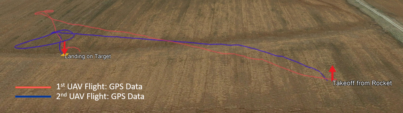
UAV Flight Sequence from Landed Rocket to Staging Area (2nd UAV Autonomous Flight)
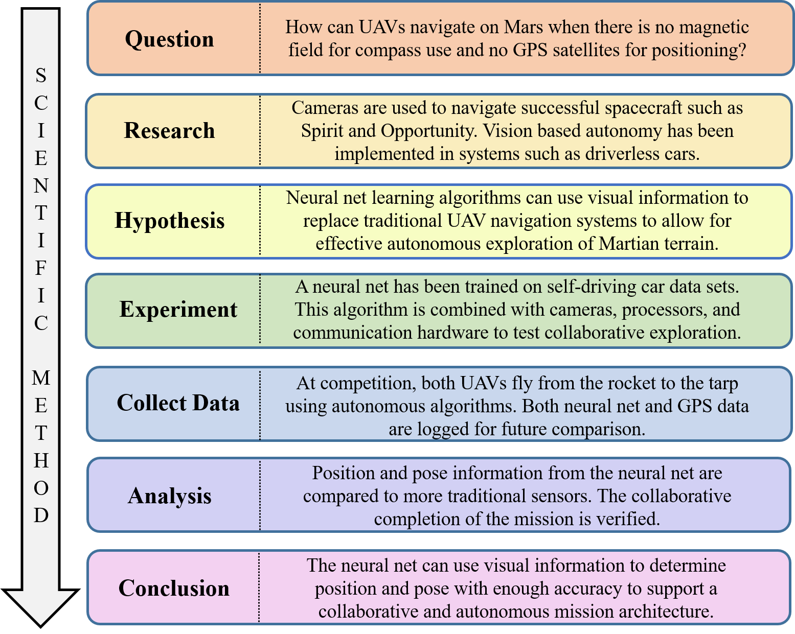
In addition to conducting autonomous flight and target detection, these UAVs used a neural net to find position and pose without the use of GPS or magnetometers. This is important for planet- agnostic exploration because there is no GPS system outside of low Earth orbit, and many planets, such as Mars, are not geologically active enough to have a strong consistent magnetic field like that of Earth. The VADL team had chosen these experimental parameters due to the exciting upcoming NASA mission: Mars 2020, which will include a large rover with a full scientific suite, and a small lightweight UAV. This rover moves slowly and can be primarily controlled by humans, but the short flight time caused by the thin Martian atmosphere necessitates that the UAV can navigate autonomously.
VADL USLI experiment
2018- Novel Two-Part Rocket Design for Remote Sensing
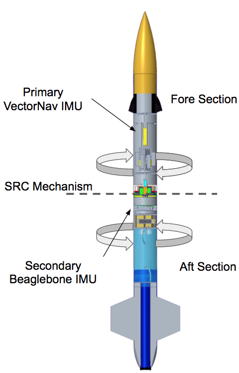
Rockets naturally roll during ascent, posing great difficulty in imaging objects on the ground. We have designed a novel two-part rocket with sectional roll control (SRC) that enables the forward payload section to steadily image ground targets while the bottom section compensates for the rocket’s natural roll.
“Stabilizing the rocket payload section to take pictures of targets as the rocket is in rapid ascent at 400 mph, and naturally rolling about its axis, is a very complicated challenge that the team has solved, said Professor Amrutur Anilkumar, director of the VADL and team adviser. “Sectional roll control can come in handy in spacecraft design for targeting, mating and servicing of spacecraft in orbit.”
Sectional Roll Control concept
Controlling the orientation of the payload section of the vehicle allows the imaging cameras to maintain the targets in the image frame. This is achieved by decoupling the fore and aft sections of the rocket and actuating the connection with a brushless DC motor.
The payload incorporates two redundant cameras, each connected to a dedicated Image Processing Unit (IPU). The two parallel IPUs locate the ground-based targets in the frame of the image. An additional single-board computer takes inputs from the IPUs and an inertial measurement unit (IMU) to calculate the distance and heading from the vehicle to the targets.
Software integration across multiple devices is a significant element of payload complexity. The ROSMOD software suite, developed at Vanderbilt’s Institute for Software Integrated Systems, provides an effective platform for inter-device communication and real-time system response. Graphics processing units are leveraged on the IPUs to improve image processing latency and throughput to provide real-time performance.
The integration of hardware and software allows the novel SRC system to respond in real-time. This helps orient the vehicle’s payload section so that the ground-based targets remain in frame throughout the duration of the flight experiment.
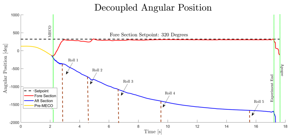
Figure showing ‘Fore Section” roll control @ fixed location and with a precision of +-2 degrees
2017 – Rocket Roll Control with Cold Gas Thrusters
The team focused primarily on rocket roll control through use of tangential cold gas thrusters. Two pairs of thrusters were used, mounted to the rocket orthogonal to the main axis and as close to the center of gravity as possible. Each pair consists of two thrusters that are 180 degrees apart and facing the same angular direction with one pair aligned for counter-clockwise rotation and the other pair aligned for clockwise rotation. The system actuated each pair independently, first inducing two full rotations about the rocket main axis then alternating the thruster couple actuation to maintain a fixed angular position.
On a high level, VADL’s payload objective is simple: creation of a system that can control the roll axis angular position of a launch vehicle. VADL’s design for this system consists of four main components:
- The plant (launch vehicle)
- The actuator (cold gas thrusters)
- The sensor (inertial measurement unit)
- The controller (microprocessor).
A microprocessor running custom control software received data from an IMU and actuated the cold gas thrusters by utilizing a custom circuit board.
Innovative Ground-Based Test Facility:
This process was aided by the development of a novel ground-based test facility that allowed for hardware-in-the-loop testing of several control schemes along with iterative testing of varied parameters within each scheme. This test facility consists of a vertical test stand isolating the full body of a launch vehicle in the primary rotation axis, with primary input from the internal thrusters as well as a disturbance input from an external motor for simulation of structurally induced rotation, side winds, jet-fin interaction, or other system disturbances. All of these components are tied together through the ROSMOD distributed system software package developed at the Vanderbilt Institute for Software Integrated Systems (ISIS), which allows for experiment development and data visualization.
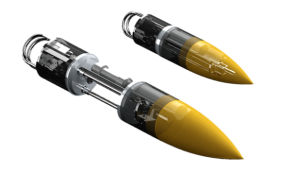
2016 – Rocket Flight-based Flight Test of a Monopropellant Reaction Control Thruster
The Vanderbilt Aerospace Design Lab’s rocket Thrustworthy carried the following payloads:
- A slosh-abating pressurized liquid propellant delivery system verified though subscale launch-based flow visualization, drop test experiments, and groundbased propulsion tests.
- Performance analysis and testing of monopropellant hydrogen peroxide thruster using iridium catalyst; flown with an inert fuel in Student Launch flight for safety purposes.
- Dynamic flight data recording system flown in various rocket subsections for launch vehicle structural analysis and comparison with finite element modelling and ground based modal testing.
The liquid fuel tank slosh abatement system was designed to provide consistent, air-free fuel to the thruster under rapid deceleration. It safely maximizes fuel extraction from a passive tank both in pulsed and continuous mode. The system has been evaluated through a linear spring and gravity based drop test stand that simulates flight conditions and through flow visualization of two tanks during subscale flights with an onboard camera system to pick the best design. It was also validated through pressurized flow testing in the team’s ground-based propulsion test stand.
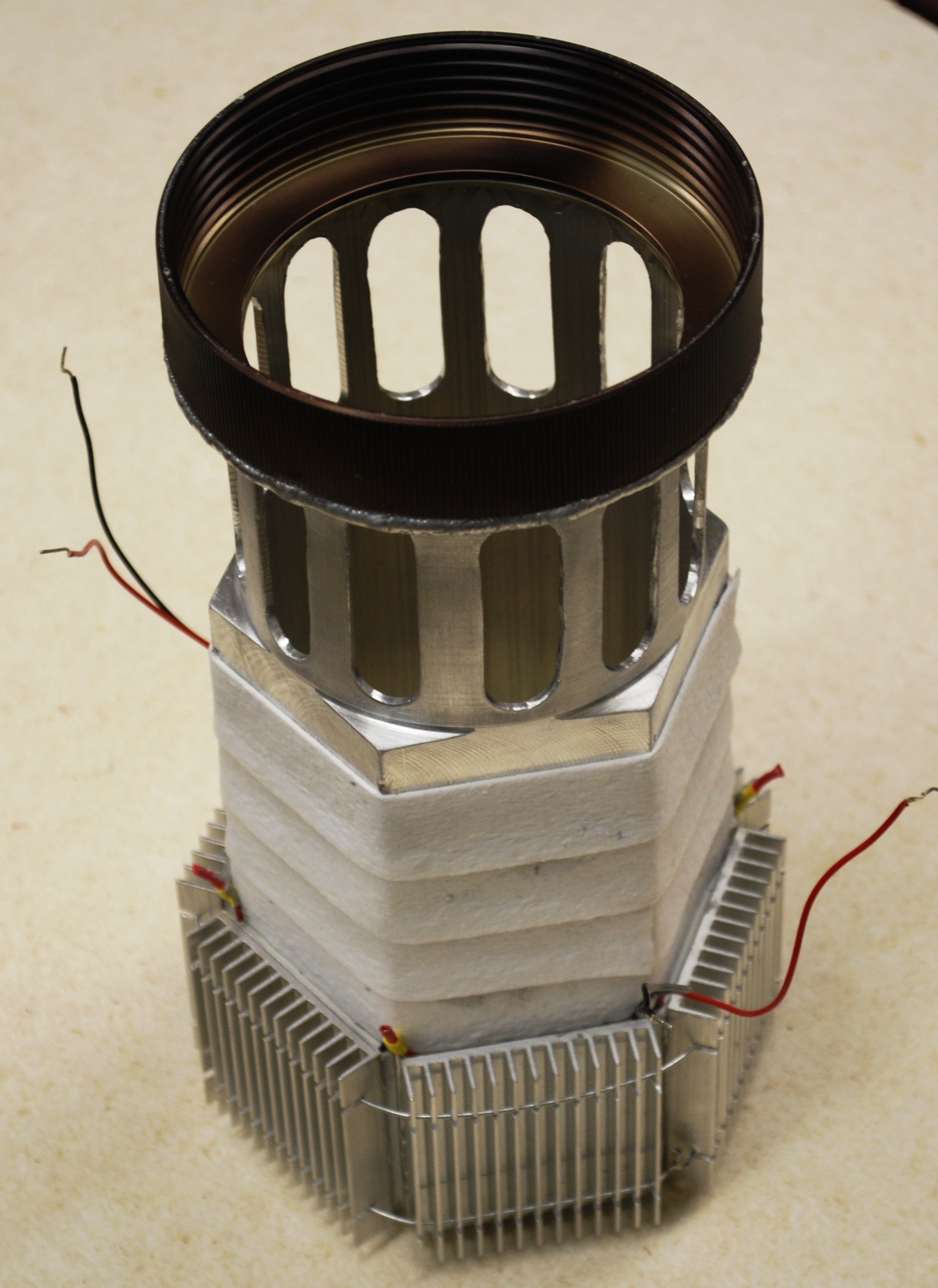
The monopropellant thruster was designed to provide a constant thrust force after main engine cutoff (MECO). It decomposes a pressurized hydrogen peroxide fluid using an iridium catalyst bed and outputs thrust through a specially designed nozzle. A ground based test facility, consisting partially of a strain gauge, pressure transducer, and fuel tank, was used to evaluate the thruster’s performance before launch and showed that it provided 10N of thrust with a neutral thrust curve in ground-based testing. Instead of the hydrogen peroxide, an inert fuel of water and soap solution was flown during Student Launch for safety reasons.
The structural analysis systems package helped develop a vehicle finite element model to represent the vehicle geometry, material properties, mass properties, and stiffness properties. This model was correlated to in-flight accelerometer data and ground based modal impact test data to increase model certainty. The correlated models were then used to analyze vehicle stresses using flight data to understand loading scenarios, and model uncertainty to optimize vehicle mass. The models predicted the frequency of the first and second bending modes to within 4% uncertainty.
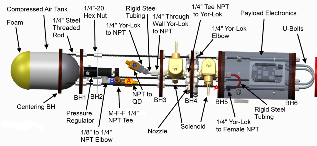
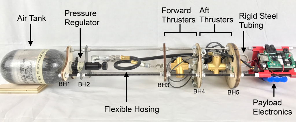
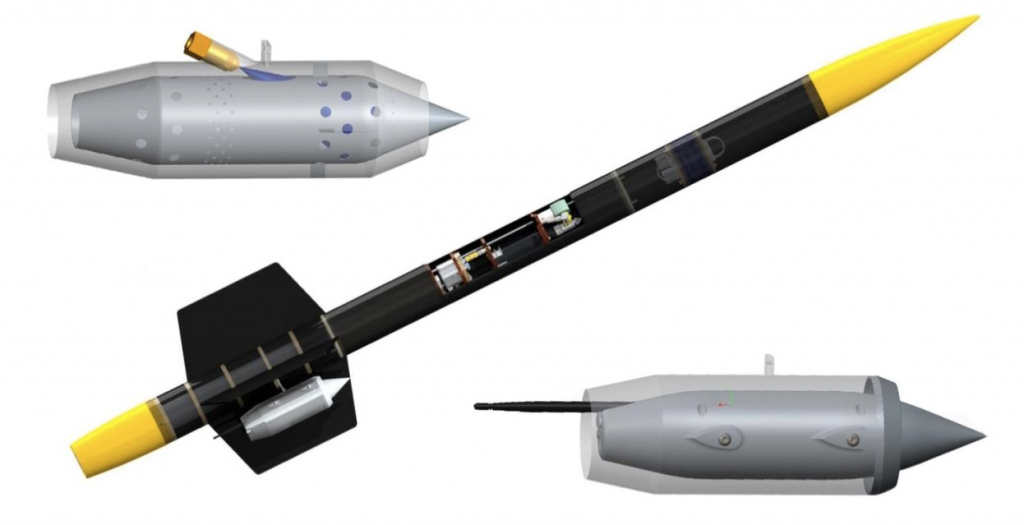
2015 – Simulated MARS Sample Return Mission and Automated Ground Support Equipment
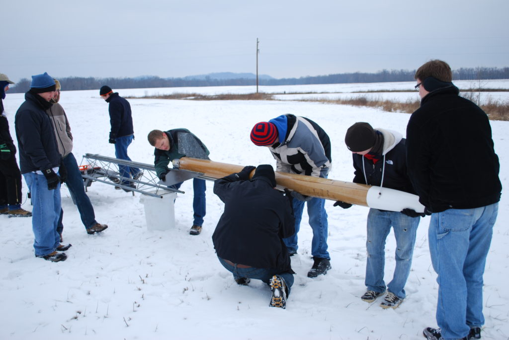
The VADL rocket, named Mini-V, had an overall length of 58.4”, with an outer body diameter of 4”, and an assembled weight of 14.55 lbs. An off-the-shelf, reloadable Cesaroni J380 “Smoky Sam” was the chosen motor, propelling the rocket to an altitude of 2929 ft. above Bragg Farms. The recovery system flown at competition was a two-parachute system, with a rocket parachute deployed at apogee and a payload parachute deployed at 1000ft. Both of these 30” elliptical parachutes were connected to their respective sections via 15 ft. shock cords. The rocket parachute was housed and deployed at apogee from the tail and forward section of the rocket (just aft of the avionics bay), whereas, the payload parachute was housed and deployed at 1000 ft. from the forward section (just fore of the avionics bay).
The payload containment mechanism is housed in the nose section of the rocket. The payload bay aims at securely storing the sample payload and then jettisoning via its own payload parachute at 1000 ft. on the way down from apogee. The payload bay design is driven by a lead screw, which acts as the method for linear actuation. By rotating against a lead nut, the motor-driven lead screw is able to securely open and close the payload bay by moving the nose cone in and out. The lead screw itself provides the force needed to secure the payload bay closed during flight—keeping the sample safely locked in place. The lead screw is non-backdrivable, meaning that axial forces, such as those experienced during launch, will not cause it to rotate against the lead nut. The payload bay contains custom aluminum bulkheads for structural support and a custom-molded carbon fiber tray and sabot system for payload retention. The payload bay houses its own electronics bay as well, providing the logic necessary for the payload bay to communicate with the AGSE during sample retrieval via a custom-made magnetic breakaway connector that attaches to the outside of the rocket.
The Autonomous Ground Support Equipment (AGSE) is a ground-based, robotic system that aims at autonomously picking up a sample payload and placing it within the rocket. Vanderbilt’s AGSE includes the additional feature of camera-based vision, an enhancement allowing for a more adaptable, dynamic system. By having computer vision, the AGSE is able to find and retrieve a sample payload from anywhere within its workspace. The camera feed informs the AGSE on where to move next, a technique in robotics called visual servoing. The image seen by the camera is processed by an NVIDIA Jetson TK1 board located on the AGSE table. Filters are applied to the image to sort out non-sample objects. Once the sample—a known geometry and color—is found, a bounding box is drawn around it, allowing the center of mass to be found. It is this center that the AGSE uses to position the gripper over the object. In a similar way, the payload bay’s position and orientation are found using two fiducial markers, similar to
QR codes, in the payload tray.
With both the sample and payload positions and orientations now known, the AGSE can pick up and place the sample in the payload bay and signal it to close. The AGSE radial and vertical movement is driven by two lead screws—influenced by the design of the payload bay. The AGSE rotates on its table base through use of a servomotor connected to its main shaft. The gripper is a custom design using a few parts from a Crust Crawler off-the-shelf gripper design. Using acrylic gear casing, metal linkages, 3D printed phalanges, and foam padding on the phalanges, the gripper has proven itself to be durable and robust not only in actuating but also in grabbing the sample. The gripper is actuated with a servomotor, as is its wrist movement.
Overall, Vanderbilt’s team has focused on optimization, reliability, and adaptability in this year’s design. The rocket and payload bay have focused on volume and mass efficiency, incorporating the smallest possible design that completes the sample recovery and launch mission. The AGSE’s ability to use camera vision to locate the sample for retrieval allows great adaptability necessary for a fully autonomous system.
These design philosophies fall directly in line with NASA’s Space Launch System Mission; the competition this year is modeled after which. Volume and mass efficiency is imperative in any Space Mission, saving fuel use and therefore money with lighter payloads. Additionally, adaptability is a critical key to a Sample Recovery Mission such as the Mars one, where a variety of extraterrestrial factors could affect the ability of the system to perform its task.
2014 – Rocket-Flight-Based Performance Study of Liquid Slosh Abatement High Pressure Fuel Delivery System through Subsonic Reverse-Flow Fuel Injection and Combustion in a Ramjet Engine, and Landing Hazard Detection Through Camjet Payload.
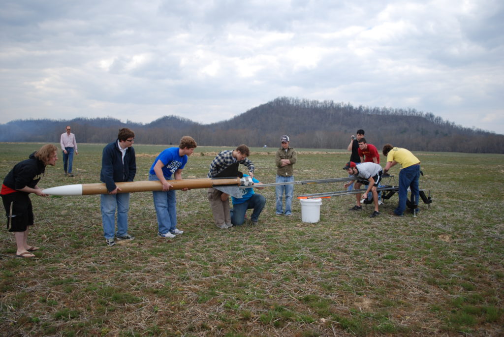
The VADL rocket, named StarCRAFT, flown at competition had an overall length of 118” with an assembled weight of 47.2 lbs. and an outer body diameter of 5.5”. An off-the-shelf, reloadable Cesaroni L1395-BS was the primary source of propulsion, propelling the rocket to an altitude of 4850 ft. above the Bonneville Salt Flats. The recovery system flown at competition was a hand-sewn dual deployment system comprising of a 12 ft. elliptical main parachute and a 3 ft. elliptical drogue connected to bulkheads via shock chords, a system that was designed and manufactured by the team. The drogue parachute was housed and deployed at apogee from the forward section of the rocket (just aft of the avionics bay) whereas the main parachute was housed and deployed at 700 ft. from the nose cone (just forward of the avionics bay).
Multiple payload experiments were performed during the competition launch. We flew liquid fuel tank slosh abatement and negative-g fuel delivery system which was validated through the performance of a high-pressure opposing fuel-injected subsonic ramjet engine running on biofuels. An aluminum fuel tank designed for safety and equipped with suitable vent valves incorporated slosh abatement measures allowing fuel to continuously be delivered at 450 psi manifold injection pressure to the ramjet for the appropriate amount of time during the flight. Sustained combustion in the active ramjet served as the final validation of the slosh abatement system. The second payload was a modular hazard detection system for landing site evaluation. The second “ramjet” shroud served as housing for this self-contained and fully modular system that contained all the necessary power and electronic components needed to collect images and perform image processing. The ramjet and the camjet pylon attachments to the rocket were instrumented to measure the aerodynamic loads on these external payloads.
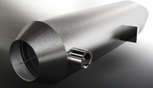
The hand-made ramjet engine is externally mounted to the aft-most section of the rocket. The ramjet will experience timely and sustained combustion of atomized fuel upon ignition, which will add energy to the air flowing through it. This hot air is forced to expand through a nozzle in which it accelerates and produces thrust. It is important to note that for this experiment, the ramjet will produce no net thrust, meaning that its drag will more than negate any thrust that is produced, and the ramjet will not accelerate the rocket beyond the means of the primary L1395 motor. The ramjet is instrumented with strain and temperature sensors to measure thrust and analyze its performance.
2013 – Rocket-Flight-based Performance Study of a Biofueled Subsonic Ramjet Engine
The objective of the Vanderbilt USLI Payload was six fold: (i) to prove that inexpensive rocket flight can serve as a test bed for the performance evaluation of air-breathing engines running on biohybrid fuels, (ii) to use comprehensive computational fluid dynamics approaches to design a ramjet engine, (iii) to hand fabricate the engine, (iv) to conduct extensive groundbased performance tests to modify and optimize the engine to work on bio-hybrid fuels, (v) to select the right biohybrid fuel blends suitable for jet engine flight, and (vi) raise awareness for the use of bio fuels in the aviation sector, as mankind has to plan for the day when renewable fuels are exhausted.
Ramjet engines are the simplest of the air-breathing engines with no moving parts, which require air compression through high-speed flight for combustion and thrust generation. The engine was first design-simulated using computational fluid dynamical tools prior to actual fabrication and testing of a prototype. We have studied different fuel injection, fuel blending, and flame holder designs and strategies to optimize the engine for flight tests. Flight test is a parametric extension of detailed groundbased tests.
Spray atomization and injection is sustained through a pressurized fuel injection system. The working pressure for fuel injection (60:40 biodiesel: bioethanol) is generated through a liquid nitrogen tank, whose vent valve has been suitably modified. At the right delay, the solenoid valve on the exit side of the cryogen tank opens, and pressurizes the main fuel tank, and the fuel is injected into the ramjet engine. Fuel delivery from the tank is started a short duration prior to the igniter burn, so as to negotiate the long delivery line.
The hand-made ramjet engines are externally mounted to the aft-most section of the rocket. They are identical and both engines are ignited. The ramjets will experience timely and sustained combustion of atomized fuel, which will add energy to the air flowing through it. This hot air is forced to expand through a nozzle in which it accelerates and produces thrust. It is important to note that for this experiment, the ramjet will produce no net thrust, meaning that its drag will more than negate any thrust that is produced, and the ramjet will not accelerate the rocket beyond the means of the primary L1115 motor. The ramjet is instrumented with strain and temperature sensors to measure thrust and analyze its performance.
2010 – Rocket-based Studies of Thermoelectric Exhaust Heat Recovery in Aerospace Engines: Design of a Thermoelectric Engine
The Vanderbilt Aerospace Club set out to design a Thermoelectric Engine for Aerospace applications. It is an engine with no moving parts which can convert some of the waste exhaust heat into usable electrical power. The concept thermoelectric engine is built using thermoelectric generators (TEG): solid state devices that can directly generate electric power across a temperature gradient. Essentially they work on the principle of the Seebeck effect which states that free charge carrier transport results from thermal transport. Older Seebeck-based devices used bimetallic junctions and were bulky while more recent devices use Bismuth Telluride (Bi2Te3)-based semiconductor p-n junctions which can have thicknesses in the millimeter range, and can be engineered to have higher energy conversion efficiencies. It was proposed that the thermoelectric engine performance can be evaluated through a rocket flight, albeit only for a short time. We argued that the rocket flight would help check out the role of flight speeds, atmospheric conditions, and launch-g effects on the design and viability of such devices and engines. The alternate test bed of a real jet engine, while necessary, can be tremendously expensive; rocket-based testing can provide a low-cost access to typical flight conditions and can serve as the first test bed for evaluation. Our extensive results from the USLI flight, which was a culmination of a year-long design, testing and development process, has clearly proved that rocket flight can be used to test out the concept design, and that flight speed has a major role in the performance efficiency of these engines.