Physics Demo Number: 107
Approximate
Run Time: 15 min
Ping-pong Ball Nuclear Fission Simulator
Demo Description
Elaborate (20+ Cubic Feet) Enclosed Structure for Putting Up To 200 Ping-pong Balls Into Confined Chaotic Motion at One Time
Scientific Principles
-
Nuclear Fission
-
Chain Reactions
Equipment
-
Dedicated Wooden Triangular Prism Base and Cart
-
Dedicated Plastic Walls and Top of Prism
-
Battery Assembly Power Supply on its own Dedicated small cart
Equipment Location
-
The Cart and Base live in SC4221-B on the left side
as you enter under Lecture Hall SC4327.
-
The Rest of the Equipment Lives next to the Cart and Base.
-
The Battery Assembly Power Supply lives with the rest,or often along the back left wall in SC4228 for Charging Access
Instructions
An apparatus housing 200 ping-pong balls sitting in vertical pairs on top of 100 powerful armed solenoids, constructed so that introduction of a 201-st ball into the device will trigger a chain reaction of rapidly moving balls, is described as follows.
1
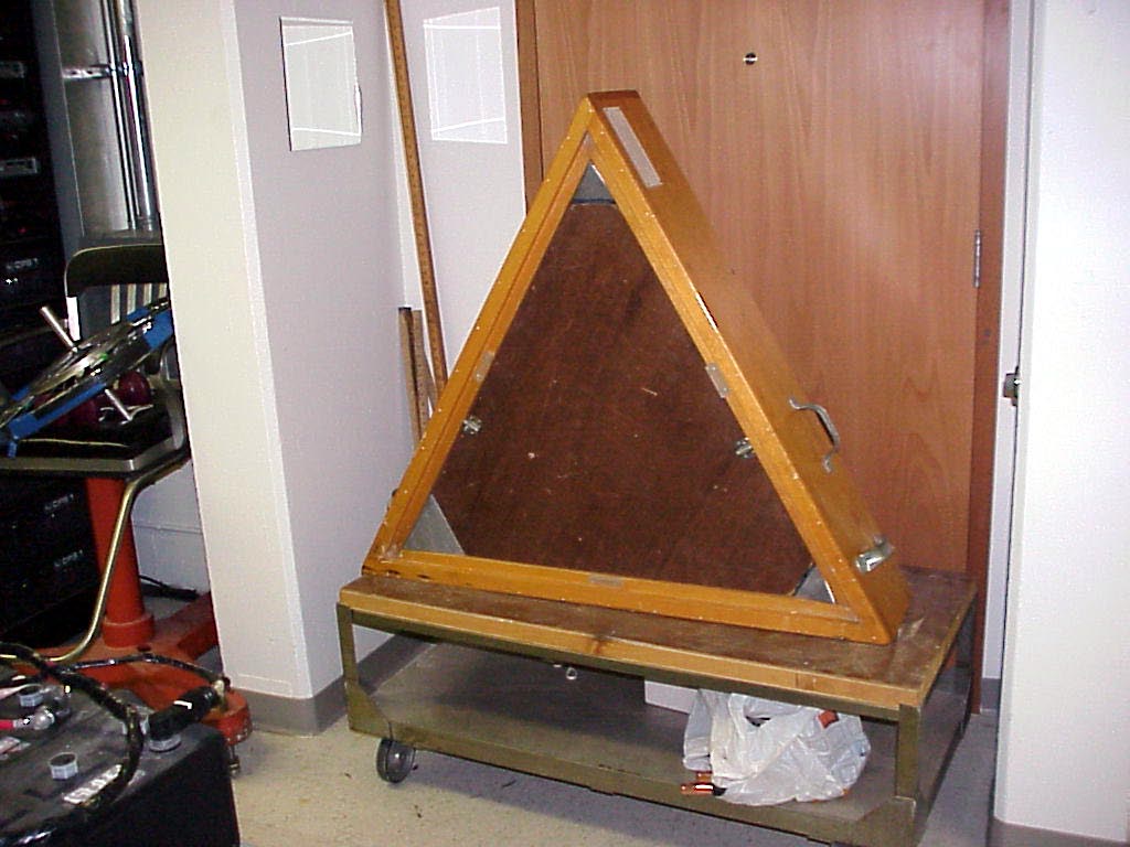
The first photo shows the Triangular Wooden Base resting on an edge on its dedicated cart.
This is the configuration for rolling to a staging area through normal doorways.
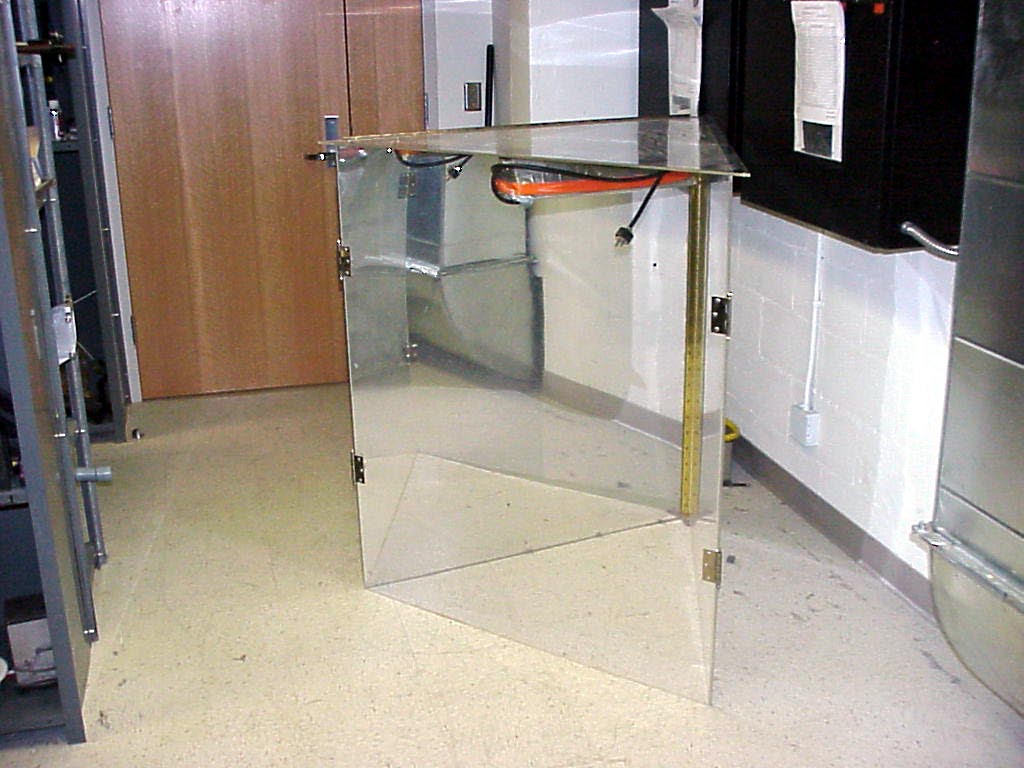
2
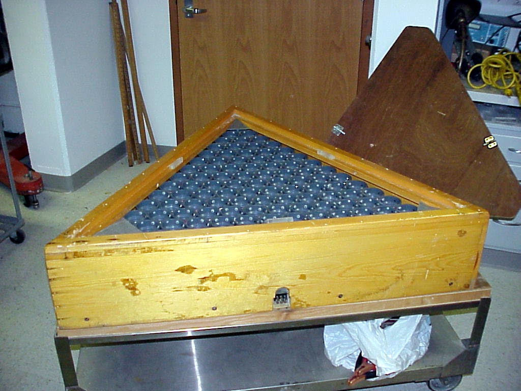
The second photo shows the Prism Base laid on its back (with the edge upon which it was resting in the first photo now vertical and aligned with a long edge of the cart). Note that the removal of the brown plywood triangular retainer sheet allows any one the 100 PVC cells, each of which contains 2 ping-pong balls , to freely discharge its contents vertically upwards should the solenoid under that cell fire.
3
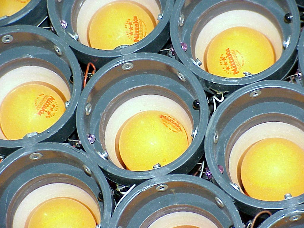
A closer view of a nested cell is provided by the third photo. One can discern that there is a photo-transistor, infrared-emitter pair wired on opposite sides of each cell.
There is a printed circuit board wired to each cell that fires a solenoid under that cell when the infrared beam at the top
of the cell is broken for 500 millisec. The two ping-pong balls resident in a cell ( along with the third beam-breaking ball ) are then propelled upwards with enough kinetic energy to rise several feet above the top of the cell.
4
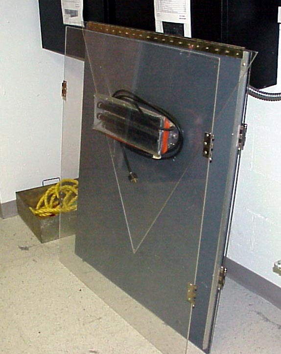
To contain the vertically rising balls one uses a plexiglass frame which is stored in compacted configuration against a wall near the storage place for the base and dedicated cart. This is shown in the fourth photo.
The fifth photo shows the configuration of the fully deployed plexiglass frame sitting on the floor rather than on the base.
5
Once deployed, one has a triangular prism about 42 inches on horizontal edges and 48 inches high.
If the collapsed frame is set on the base and opened up from there ( a two person minimum job),
the tip of the frame's top face must have about 10 feet from the floor overhead clearance to swing it
up (subject to the constraints of its hinged connection to the mirrored back face) from its compacted vertical position and over a full 270 degrees into its new horizontal position as the horizontal top of the newly created triangular frame.
Given the low overhead clearances in SC4228, it is easier for two people to deploy the frame on
the floor as in photo 5, and then lift the frame onto the base (which is already configured on its cart
as shown in photo 2.
The back face of the prism is a mirrored sheet and needs to end up along the edge of the base facing us in the second photo.
Note that there is a special electrical socket embedded in this base edge. This is the connection point for the wiring harness of the dedicated “three-truck-battery”-“power-supply-on-wheels”shown in the sixth photo.
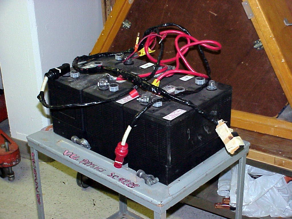
6
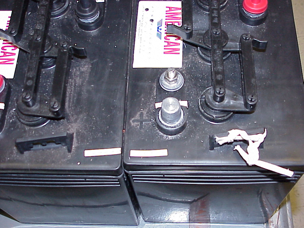
Very important details of the redressed harness are shown in the seventh photo, below.
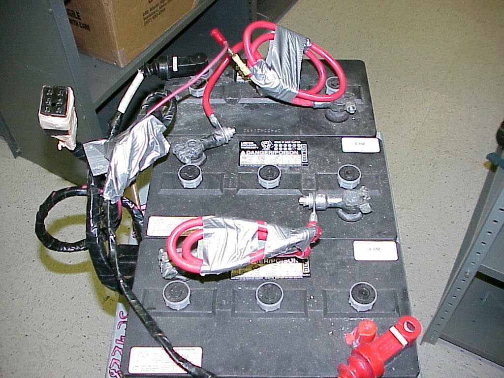
7
The black connector on the upper left in the seventh photo plugs into the mating socket
described above.
The red banana plug male end in the upper center of the photo is shown plugged into the
yellow female receptacle (which is hard-wired to the battery cable accessory wire )
coming out of the dedicated battery cable end pictured in top right.
This last connection arms the trigger circuits for the infrared photobeam pairs, and is thus
a safety key to keep explosions of flying ping pong balls from hitting you in the face or
scattering balls all over the floor.
It also serves as the low-voltage , low-amperage on/off switch for the reaction, avoiding
dangerous arcing that would occur if you tried connecting or disconnecting the battery cables
directly while 100+ ampere loads are being supplied.
The red quick connect battery cable on lower right must be hooked up when making a run.
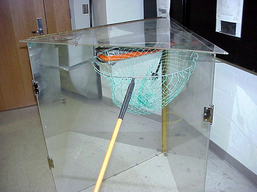
8
The above photo shows a butterfly net which can be used to capture balls in motion to slow down the reaction rate.
The two following photos show wiews of the batteries in pairs with the connecting wires removed.
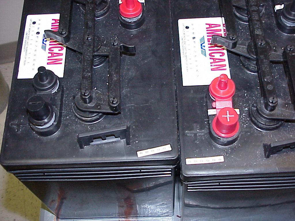
Labels have been added to the batteries and terminals and big connecting wires so that they may be carefully returned to the state of the 7th photo.
However from this date ( 14 June 2012 ) forward the batteries and their cart will reside in 4221B
(with a protective box over their terminals) and the big connecting cables stored on a fixture attached to the cart.
The batteries (with their cables removed and their cart) are being moved to inactive storage with the cart for the main apparatus base , since the demo
1) is seldomly used and
2) there is concern over the safety of the batteries stored in a ready to use mode.
Any desired faculty use of the demo must be arranged at least a week or two in advance of the planned date.
Notes:
-
Unfortunately the architects left the door width from the prep room into each of the
big lecture halls about 2 inches too small for the base to be wheeled into either lecture
hall in its assembled-for-use horizontal configuration.
-
Thus a time-consuming trip out of the SC4228 door to the prep room, then down the halls and around for an entry into the main-corridor second level lecture hall doors is needed to get the assembled beast into the lecture halls.
-
The apparatus will not function if infrared components are present in the ambient
lighting of the lecture room. Thus avoid outside light through windows and
incandescent lights turned on in the room.
-
There is a back light fixture affixed to the top of the plexiglass frame which may be
turned on to add an eerie visual component to the display, since the orange balls fluoresce
under the black light.
-
The panel that the butterfly net is leaning against in the eighth photo can be replaced with
an optional mirrored panel, to let the apparent swarm of balls look like 18 to 1206 instead
of 6 to 402 with the single backing mirror. This works only for small groups ( so that everyone can look in through the one clear panel easily).
Writeup created by David A. Burba
Copyright © 2013, Vanderbilt University. All Rights Reserved.