Physics Demo Number: 043 |
Approximate Run Time:10 min |
|||
Electrostatics With The Aid of Van de Graaff Generators |
||||
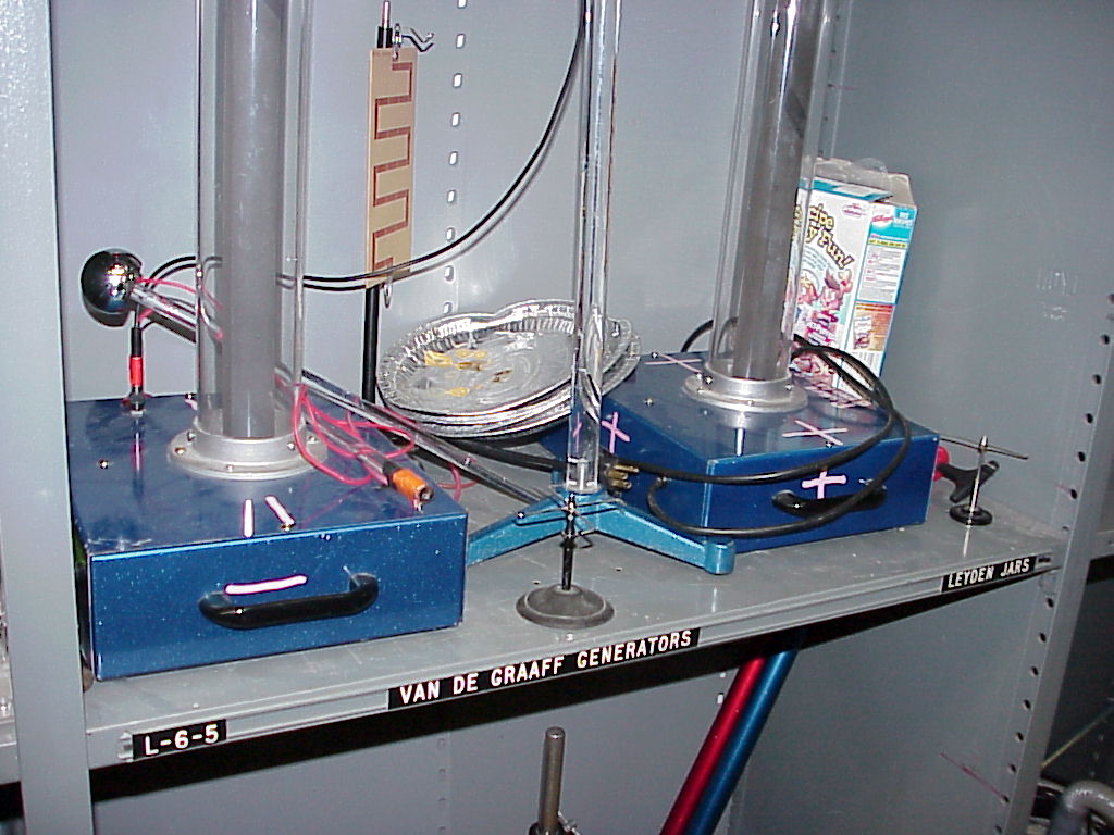
Demo DescriptionUse a Van de Graaff generator to mechanically separate charge. To display the charge: 1) There are pie pans that can be made to levitate. 2) There are rice cereal bits that can be used to display a shower of charged particles. 3) There is a whirligig that spins like a water sprinkler.
4) There is a printed circuit board on an insulating stand
with a path of small jump gaps from the
top of the board to its bottom. |
|
Scientific Principles
|
||
|
Equipment
|
1
|
|||
Equipment Location |
||||
2
|
3
|
|||
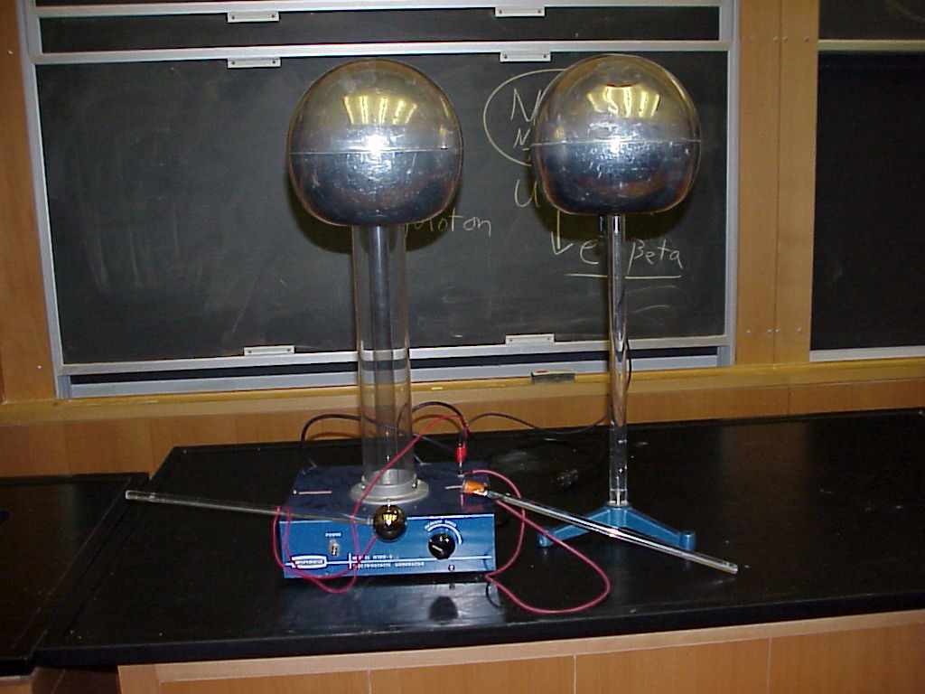
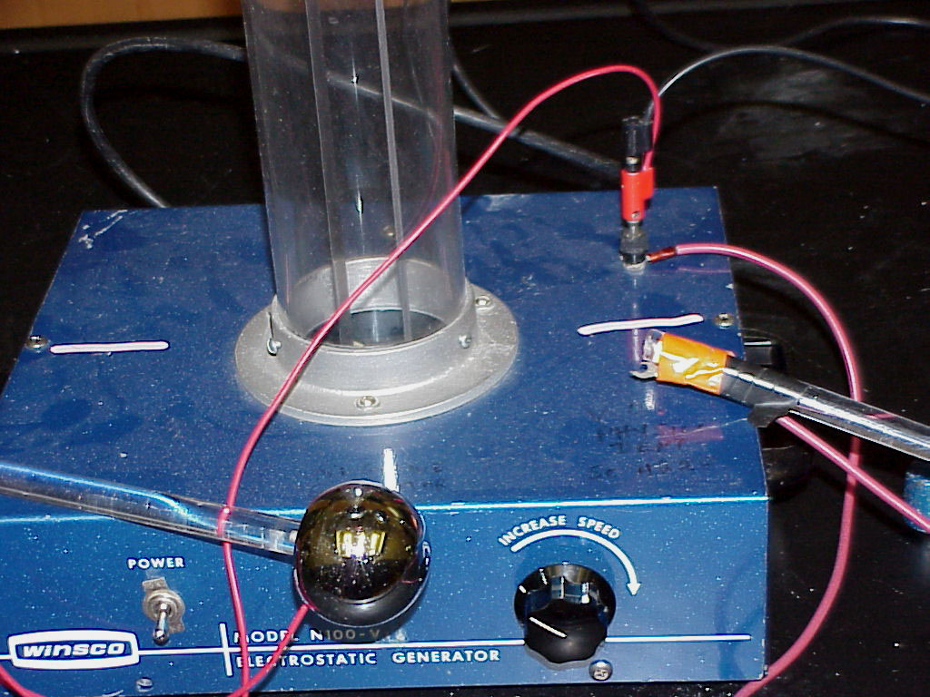
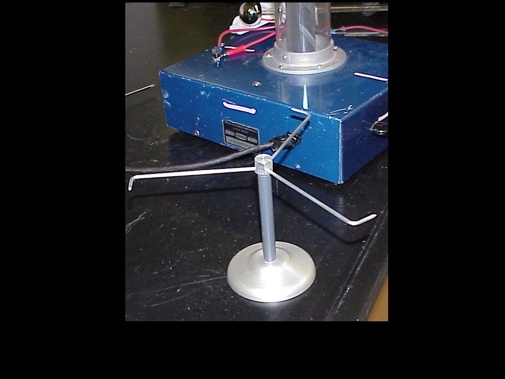
InstructionsPicture 1 shows the basic generator apparatus. The printed circuit board (in the rear, next to pie pans) can be used to show lots of eye-catching sparks jumping gaps as current follows the path of least resistance to ground. The pie pans can be stacked on top of the generator and will levitate off when they become charged. Rice Crispies can be stacked on top of the generator to provide a shower of particles as they become charged. A four-pronged whirligig (in the center front) will spin like a water sprinkler when attached to the generator. The just mentioned four-pronged whirligig has become problematic to keep working and has been replaced by a three-pronged whirligig seen in the two pictures below. One simply holds the new whirligig by hand up near the running generator dome. The usage will not shock you thanks to the three sharp points. ( Do you have enough faith in the Physics not to flinch? ) Picture 2 shows the typical setup to draw long, noisy sparks from the generator to a big spherical capacitor. Picture 3 shows the details of the recommended set up. Note that three wires are attached to the black ground terminal at the right rear of the generator's top surface. The black wire runs to the belly of the spherical capacitor. The upper red wire runs to the small diameter spherical grounding surface, which is attached to an insulating rod for the demonstrator's hand. The lower red wire runs to a sharp-pointed spade-lug which is taped to an insulating rod for the demonstrator's hand. Calling the last two mentioned devices “grounding rods”, one should use the sharp-pointed rod to ground the sphere of the generator before touching the controls. The spherical grounding rod can be used to draw sparks while the generator is running. The sharp-pointed rod must be kept at the level of the lecture table to allow normal functioning of the generator.
|
||||
Writeup created by David A. BurbaCopyright © 2013, Vanderbilt University. All Rights Reserved. |
||||