Physics Demo Number: 127

Approximate Run Time: 15 min

Diffraction From The Steel Rulings on a Machinist's Ruler

aka: Measure the Speed of Light with A Ruler
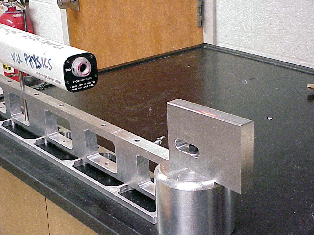
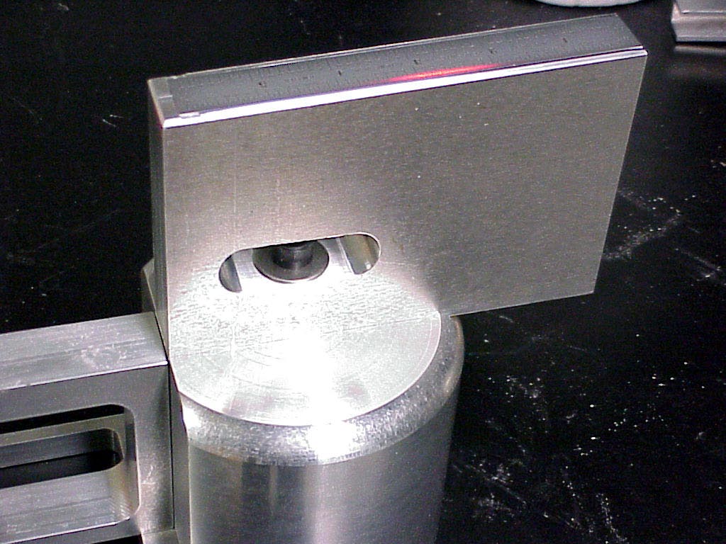
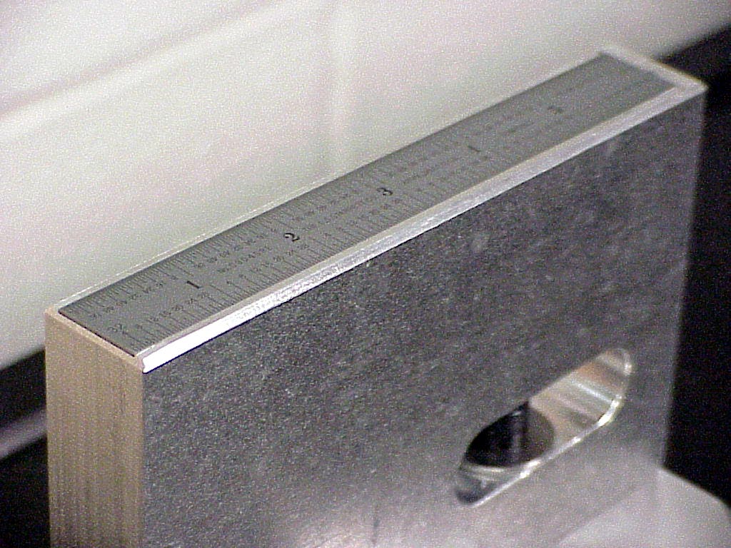
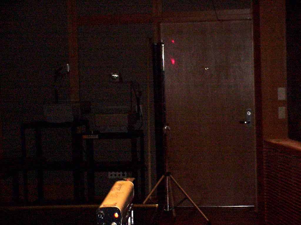
Demo Description

A dedicated fixture for holding a 6 inch Machinist's rule precisely aligned with a laser allows one to reflect the beam off the rule and observe the diffraction spots from the rule's markings on the wall. One can then determine the wavelength of the light quite accurately from direct measurements of the distances involved.


Scientific Principles

  • Reflection gratings can form diffraction patterns even without having to use an expensive dedicated ruling, if the light is intense enough, coherent enough, and one has sufficient room for the pattern to spread out for convenient measurements.

Equipment

  • 5 mw HeNe laser and stand

  • Machinist's Ruler and Holder

  • 10 M Tape Measure


Equipment Location

  • The laser and its holder are on [C-2-4].

  • The rest of the components are in Kit (127) on [C-2-2].

1


2


3


4


Instructions

The first picture shows the 5 mw He-Ne laser and stand along with a free standing Science-Shop-made dedicated metal ruler holder.

The ruler holder has been constructed to allow a couple of inches of the ruler's engraved markings to be illuminated by the horizontal laser beam and reflected onto the prep room door.

A closer view of the ruler and its holder (automatically indexed to the end of the Laser holding stand) is seen in the second photo.

The third photo gives a more detailed look at the ruler resting in its dedicated, inclined groove atop its holder base.

The reflected beam elements travel approximately 7m to form a specular reflection and various diffraction maxima on the prep room door , as seen in the fourth photo.

The two laser spots in the photo correspond to the specular reflection image (lower dot) and the first maximum of the diffraction pattern (upper dot).

Define A to be the angle between the horizontal and the line straight from the middle of the laser illumination on the rule to the lower dot . Similarly define D to be the angle between the horizontal and the line straight to the upper dot . Then if the ruling spacing on the steel ruler is d, one has the wavelength of the laser given by

d cos(A/2) – d cos[D-(A/2)].

Simple measurements of the distances of these two dots above the floor and the distance of the horizontal laser beam above the floor allow angles A and D to be calculated and thus the above expression for wavelength to be evaluated and compared to the accepted value of 0.00006328 cm.

Note that due to slop in the laser's threaded hole for accepting its mounting rod, the end of the laser stand nearer the laser may have to be shimmed up by about a thickness of a 50 g slotted brass mass to achieve a perfectly horizontal path for the laser beam over the 7 m or so to the door on which the reflected and diffracted spots are formed.


Writeup created by David A. Burba
Copyright © 2011, Vanderbilt University.   All Rights Reserved.