Physics Demo Number: 123
Approximate
Run Time: 20 min
Ripple Tank Wave Demonstrator
Demo Description
Set up a large ripple tank and try to achieve visible wave patterns for class to view on front A/V interface screen.
Scientific Principles
-
Disturbances on a water surface can generate observable waves.
Equipment
-
Two dedicated wave-generating motors on their dedicated support rods and heavy rectangular-parallelepiped bases.
-
The dedicated light source (set in point source mode) with its dedicated support rod and heavy circular base.
-
A dedicated power supply and controller
-
The tank itself.
Equipment Location
-
[F-4-2] is the dedicated bin shelf for demo(123).
-
All equipment resides on [F-4-2], some of it in two Kits. See note below.
-
The optional video camera lives on a cart against the wall upon which the large ladder hangs.
Instructions
Note that this is a very involved demo to set up and do. It is probably too time consuming for using in a normal class lecture.
In keeping
with the above remark, we have moved the apparatus to the elementary
lab storeroom to join its duplicate set of equipment for use as a
set of lab equipment for two groups of students.
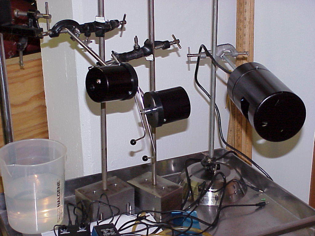
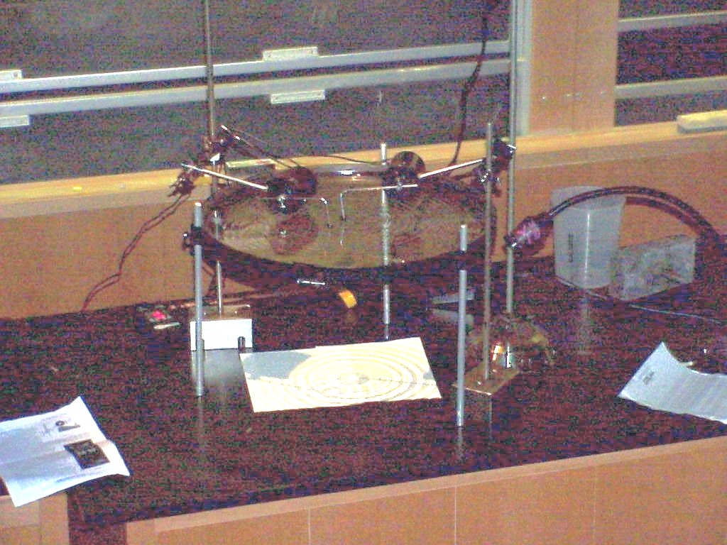
The first photo shows the major components for generating and viewing waves in the large ripple tank.
These components are from left to right:
1.) two wave-generating motors on their dedicated support rods and heavy rectangular-parallelepiped bases
2.) the light source (set in point source mode) with its dedicated support rod and heavy circular base.
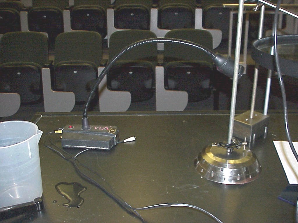
The next photo shows the details of electrical hookup.
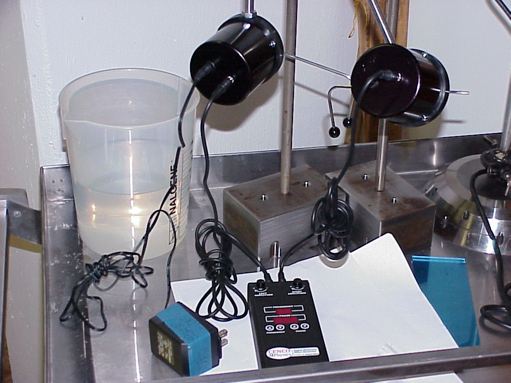
The
transformer power supply on the bottom left feeds into the back of
one wave-generator motor .
A connecting wire runs from that motor's other terminal to the black control box.
The other connecting wire runs from the black control box to the second wave-generator motor.
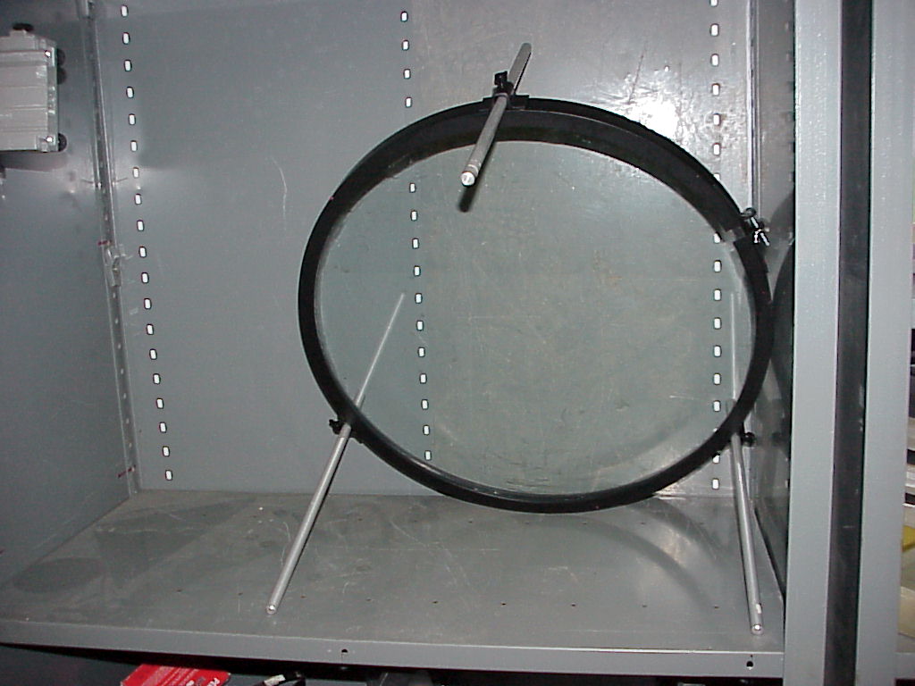
The ripple tank itself is seen in the next photo (at rest in a bin after removal from its protective wooden box and insertion of its three legs from Kit(123)B):
The
next photo shows the components in place and working in two point
wave source mode.
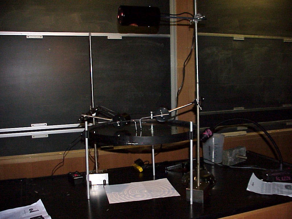
The
circles on the white paper under the tank are actual shadows of
the wave pattern with the light source in its point source
position.
These circles are clearly visible to the unaided eye from anywhere in the room (SC4327).
Note that a goose-neck compact video camera (from the cart against the wall behind desk) has been set up on the right side of the tank and focused on the patterns on the paper.
A more detailed look at the patterns on the paper and the goose-neck camera's placement is in the next photo.
The output of the camera to the lecture hall interface is shown next.
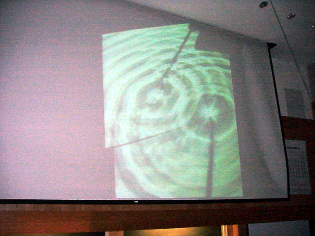
This
view is introduced to the Lecture Hall Interface by the electrical
linkage shown in the following two photos:
First the camera end:
Now the interface end:
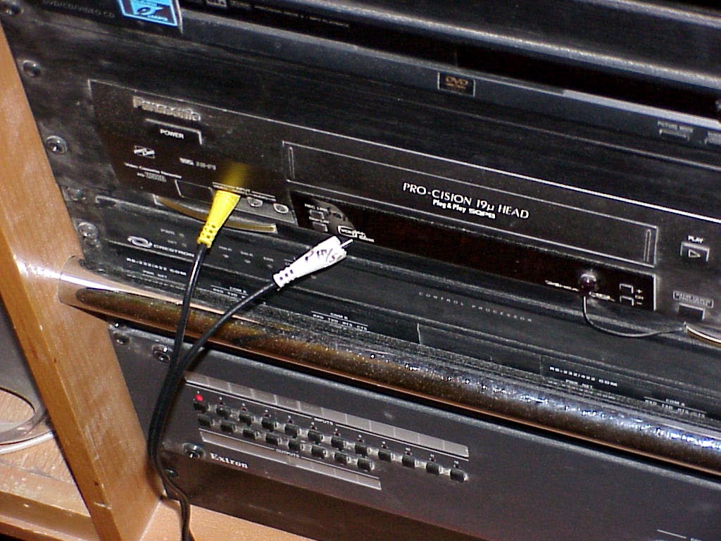
Control
wise, one selects F-1 at the VCR and chooses VCR Play at the room
interface screen.
Writeup created by David A. Burba
Copyright © 2011, Vanderbilt University. All Rights Reserved.