Equipment & Set Up
|
|
Equipment Location
|
InstructionsPLEASE note that this demonstration is quite intensive in time used, especially for large classes. Among other things, one must fill the LN2 pans completely in real time in class and be prepared to set the chamber off of the base and refill the pans again.
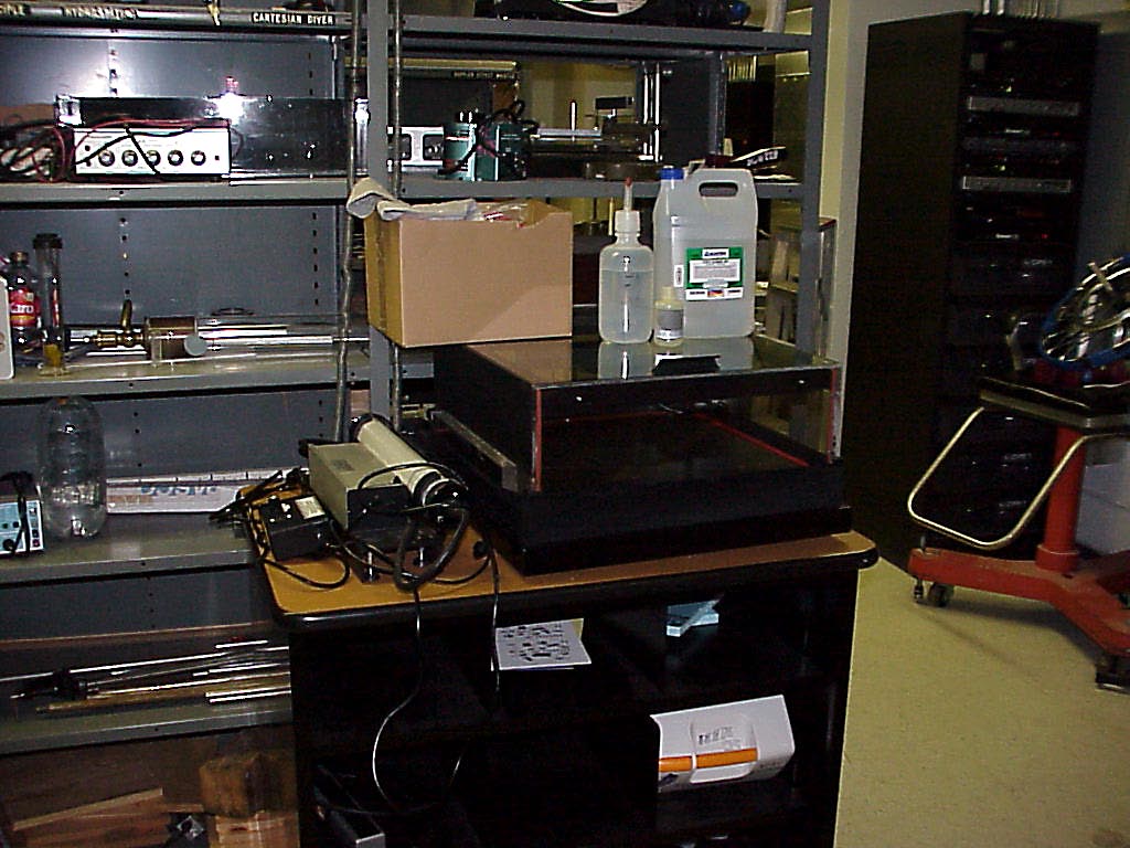
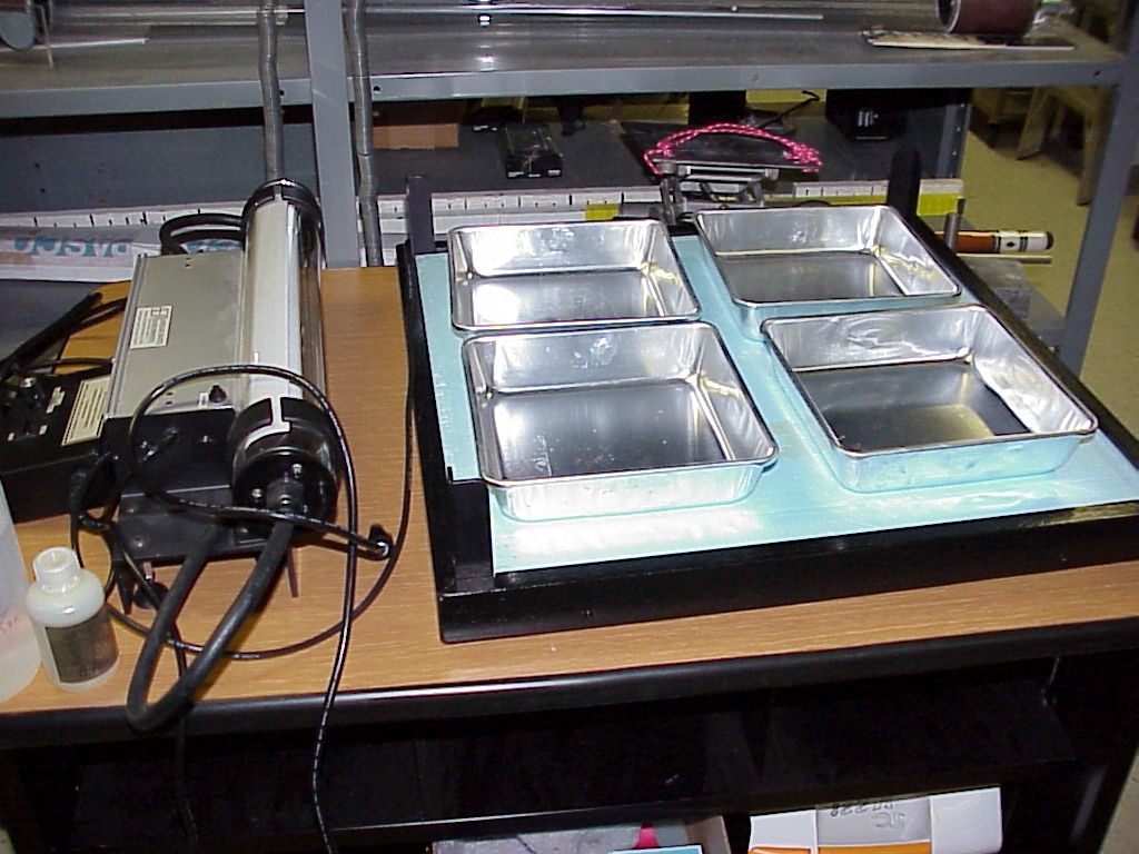
Other components are stored in the shelves of cart.
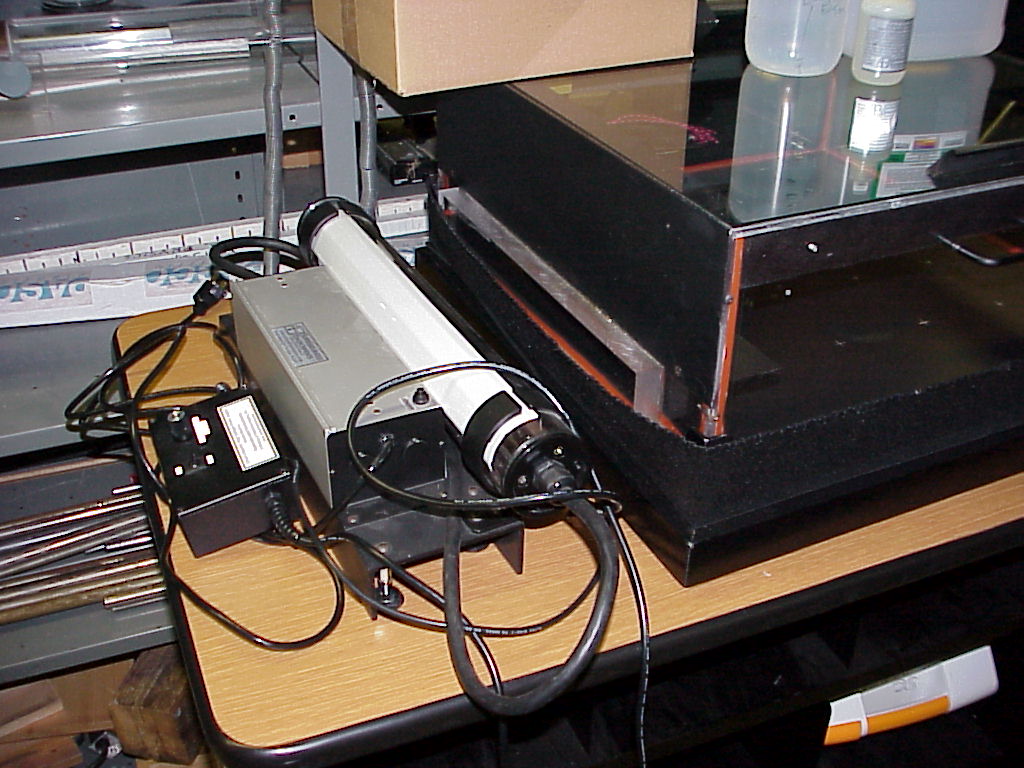
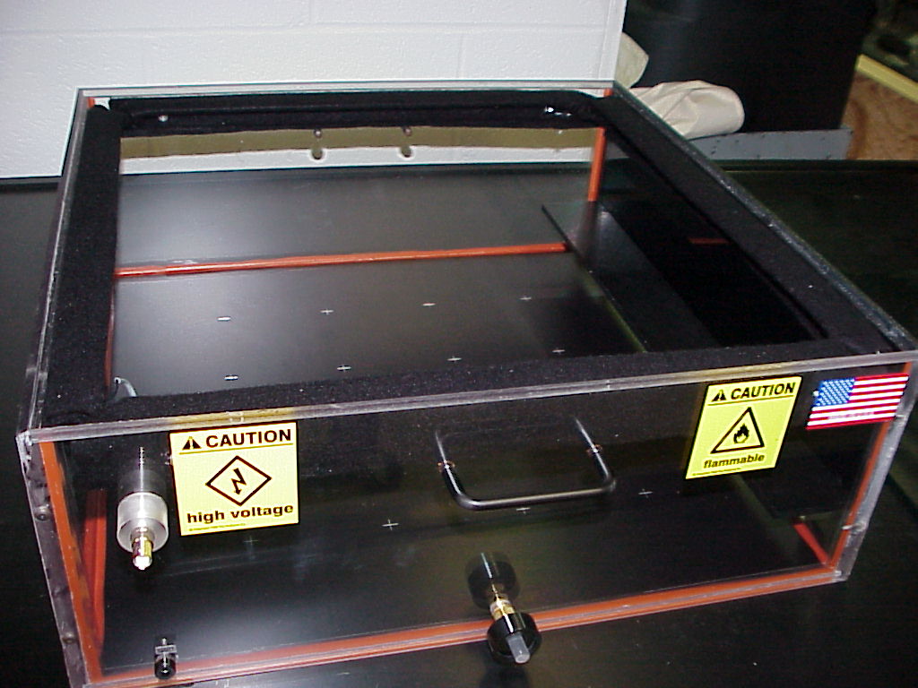
1) the light source for viewing of tracks 2) the high voltage supply (for a vertical electric field in the sensitive volume during chamber operation) 3) the bottle of anti-fog compound for treating the top surface of the chamber body's glass top before cooling starts.
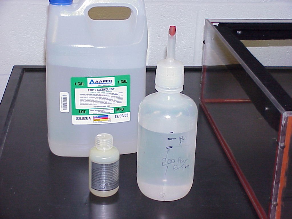
(Once the felt edges are thoroughly saturated with the ethanol, one pours the remaining part of the pint(+) solution into the bottom of the chamber body.)
The skirt is placed around the bottom of the chamber body to seal out air currents between the chamber body and the foundation. Cutting down on air currents allows the liquid nitrogen to do its cooling job longer.
Various radioactive sources are in the brown box in the cart shelves area. Writeup created by David A. BurbaCopyright © 2013, Vanderbilt University. All Rights Reserved. |
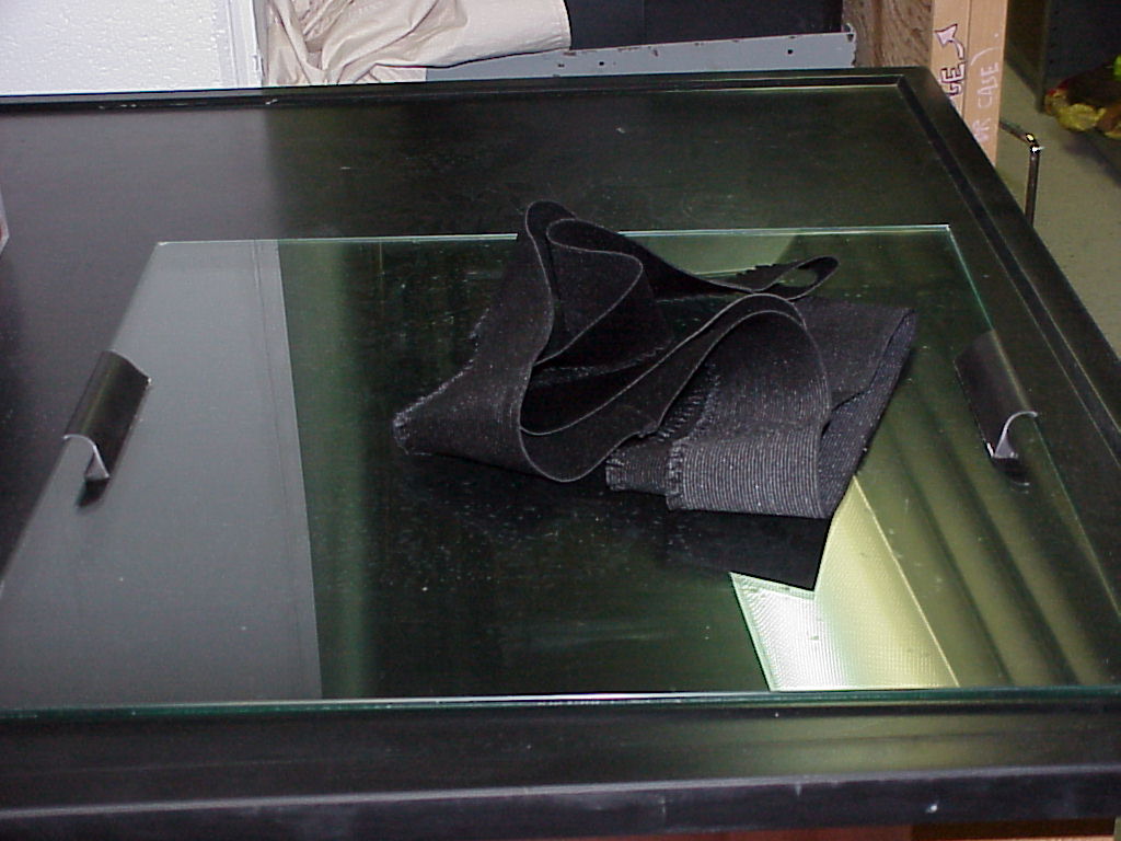
 One
must place the chamber body itself, seen in the third photo, on
top of its cold foundation after having poured a (80 to 90)%
200- Proof Ethanol / (20 to 10)% Water solution on the felt
which runs all the way around the top edges of the chamber body.
One
must place the chamber body itself, seen in the third photo, on
top of its cold foundation after having poured a (80 to 90)%
200- Proof Ethanol / (20 to 10)% Water solution on the felt
which runs all the way around the top edges of the chamber body.