Instructions
The first
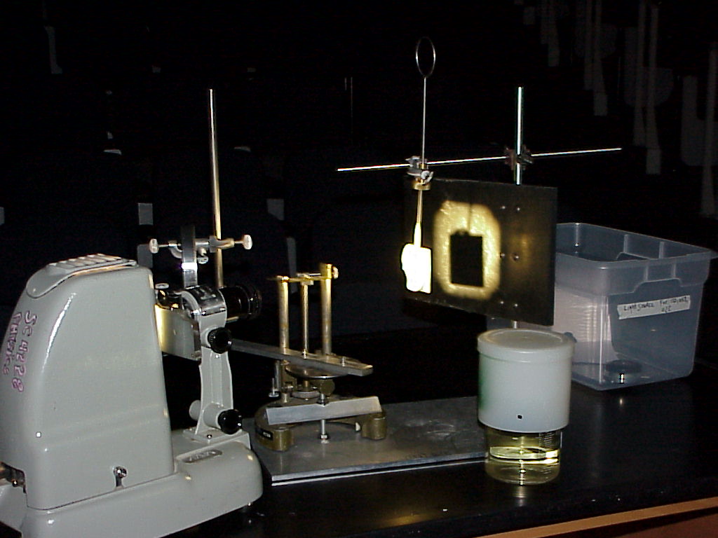
photo (1) shows the usual light source (old slide projector ) on the
left.
The adjustable
lens-support-assembly , coin-bearing wire-loop assembly , and
excess projector-beam baffle assembly are seen on the right, all
permanently attached to their dedicated metal base.
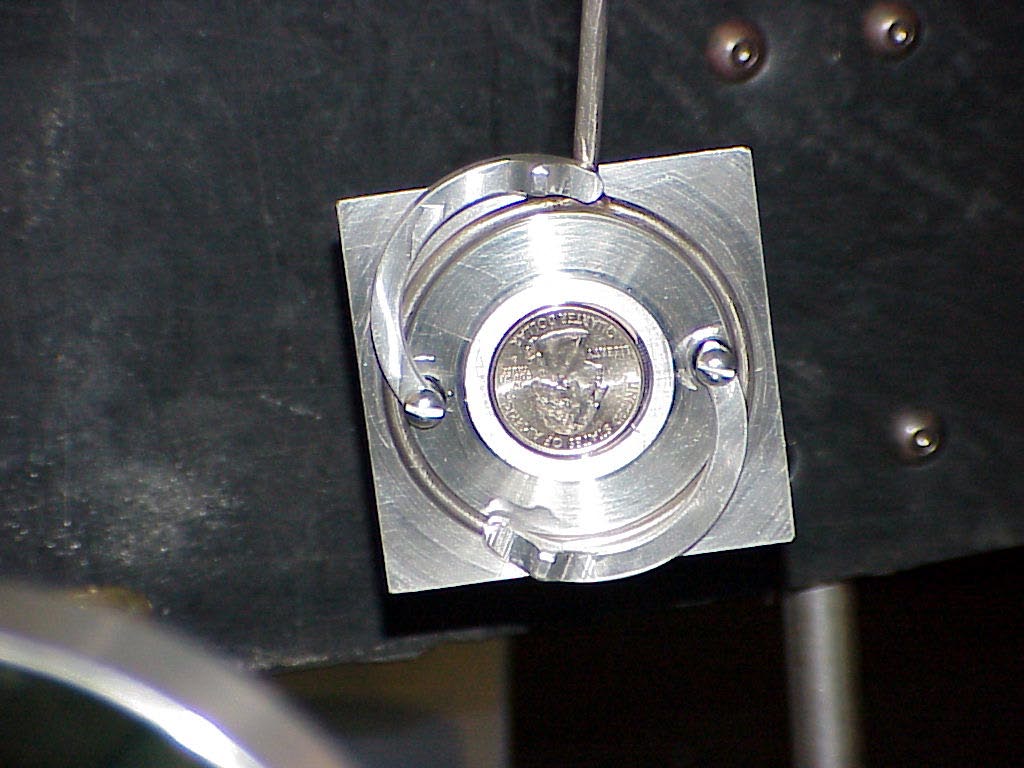
The second photo (2) gives
the appearance of the coin as seen from the projector's
view-point, in its elegant Science Shop made mounting.
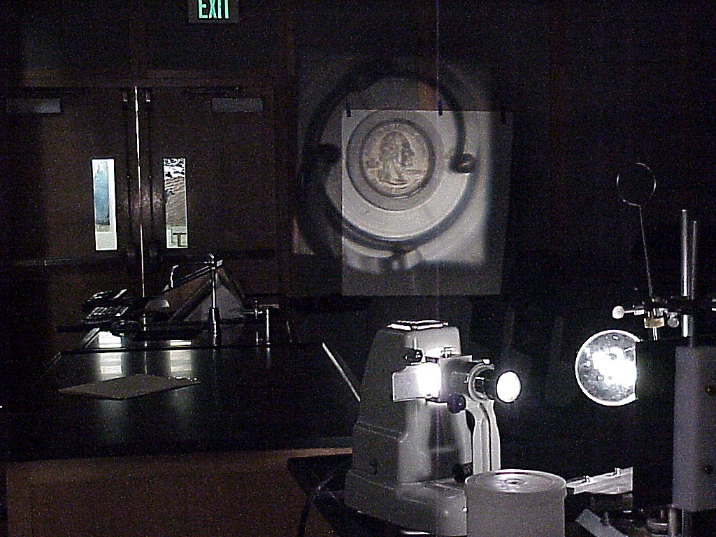
The third photo (3) captures
the demonstration in action with the reflected light from the
coin being focused on the foam screen (from the coat rack between
the two desk areas) , which is leaning against the lecture hall
corridor wall 7 or 8 meters behind the lens.
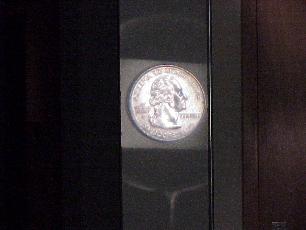
The fourth photo (4) is
typical of an image on a surface a couple of meters from the
lens.
[Note: The Science Shop
has helped us design and make a nice new metal holder for the
coin. The metal holder is now permanently replacing the old tape holder.]
Note that in (4) 's real image on the wall, Washington is right
side up , but facing the wrong way. Also the writing is
“backwards” or mirror image.
Since a converging lens
inverts up-down and effectively perverts left-right, the only thing wrong
with this state of affairs is that Washington would have been
expected to be upside down in the image.
In fact Washington was
put on the wire-loop assembly upside down, as documented in (2).
If one places the
apparatus about at the center of the stage area and achieves the
image on the hall side wall, then the people along that wall may
have a poor view, but everyone else will see the view in (4).
However one may now
intercept the light leaving the lens with the plane mirror and
reflect it back to the prep room side wall.
Now one has a real image
with Washington facing the normal way and the writing on the coin
normal.
One has moreover achieved
a real image with a plane mirror ( by giving it a virtual
object).
Writeup created by David A. Burba
Copyright
© 2013, Vanderbilt University. All Rights Reserved.
|