Instructions
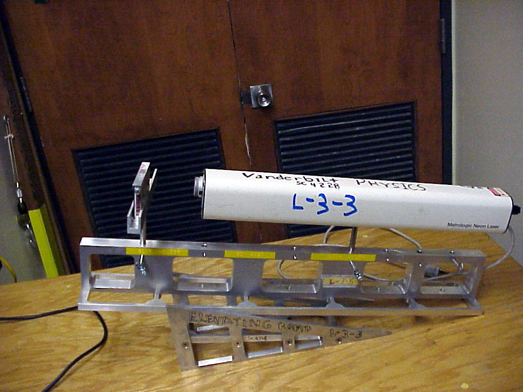
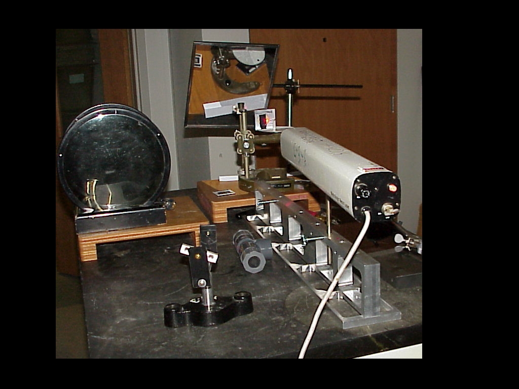
The
top photo shows the HeNe laser apparatus used to create single
and/or double slit patterns on the wall (or screen) in the
classroom.
The
shop-made ramp and holders allow for the precise horizontal and
vertical alignment of the laser beam on the slit module(s)
and the vertical positioning of the entire pattern on wall.
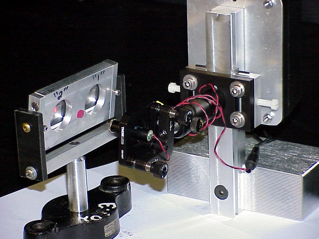
The third photo shows the more convenient Diode Laser setup.
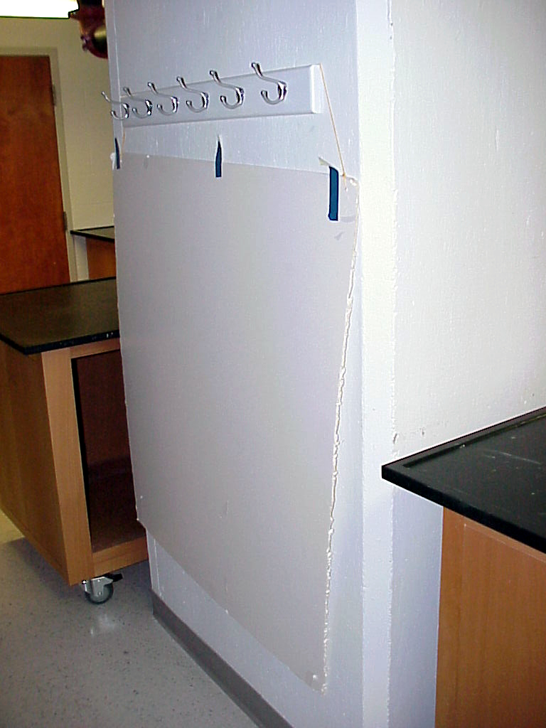
The second photo shows the Foam Board hanging in its home position.
Note
that the dedicated yellow cord attached to the board can be hung
on a lecture hall chalk-board and the chalk-board then raised to
give the level of foam board desired. One may also just set the
foam board in a chalk tray.
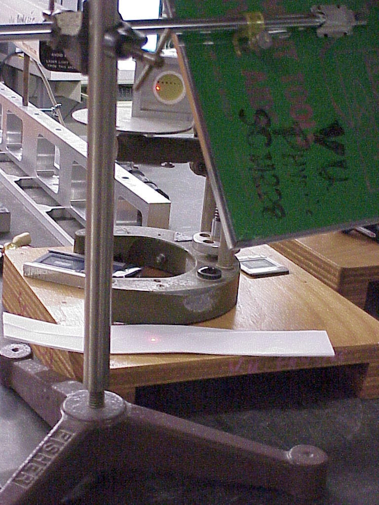
Photos four and five show the set up and equipment for showing the diffraction pattern of a small hole.
Photo four looks toward the laser and the brass plate with the small hole. One can see the laser light coming through the hole.
This light is reflected from the angled plane mirror (whose green backside is seen at the right of the photo).
Note
that the actual diffraction pattern may be glimpsed on the white paper
(which lies in the foreground of the photo) on the wood riser table.
Photo five gives the setup of photo four seen from the laser end.
The
idea of this setup is to get the diffraction pattern of the hole
onto the staging surface of the document camera, so that a visible
large image may be placed onto the lecture hall screen using the zoom feature and manual focusing of the document camera.
This
is a very tedious and demanding trick to pull off and will require a
big chunk of time and effort on the part of the instuctor to practice
ahead of time.
|